WHITE PAPER
Formlabs Logo

Replacing the Fuse Sift mixer assembly

Replacing the Fuse Sift mixer assembly

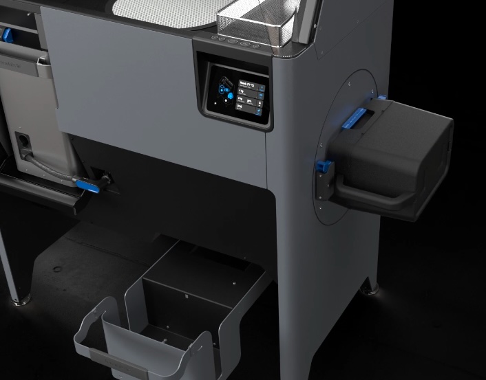
The Fuse Sift mixer mixes your powder cartridges, ensuring a homogeneous mix of fresh and used powder. A faulty or malfunctioning mixer will make it more difficult to mix and reuse powder.
Use this guide to replace the Fuse Sift mixer assembly.

Fuse Sift mixer

Required supplies:

Formlabs:

Third-party:

  • 2.5 mm hex driver (flat-end)
  • 3.0 mm hex driver (flat-end)
  • 7.0 mm compact socket wrench (recommended) or box wrench
  • Antistatic wristband
  • Flush cutters
  • Zip tie
  • Spirit level
  • Loctite 243 or equivalent threadlocker
  • Appropriate personal protective equipment for the powder in use, as defined in the safety data sheet (SDS)

Estimated time: 45–60 minutes

Preparing the workspace

Overview: Prepare the Fuse Sift and your workspace for replacing the mixer assembly.

Step 1: Remove and store printed parts

Remove any printed parts from the Fuse Sift workspace to prevent them from being damaged inadvertently.

Step 2: Clean the workspace

Using the vacuum attached to your Fuse Sift, clean the workspace. Vacuum any loose powder inside the workspace, under the hood, on the print bed and the surrounding port, and on the vent filter.
Step 3: Unplug the Fuse Sift

Power off the Fuse Sift, then unplug the power cable from the rear panel.
Danger:

Performing this procedure on the Fuse Sift while it is plugged in increases the risk of electric shock. After disconnecting the power from the Fuse Sift, wait at least five minutes before servicing.

Step 4: Unscrew the Wi-Fi antenna

Remove the Wi-Fi antenna, if present.

Warning:

Use appropriate personal protective equipment when handling loose or unsintered powder. Refer to the support article Safety with Formlabs SLS products or your powder’s safety data sheet (SDS) for more information.

Removing the upper front enclosure panel

Overview: Remove the upper front enclosure panel to access the display assembly mounting screws.

Step 1: Unscrew the upper front enclosure panel mounting screws

Remove the upper front enclosure panel

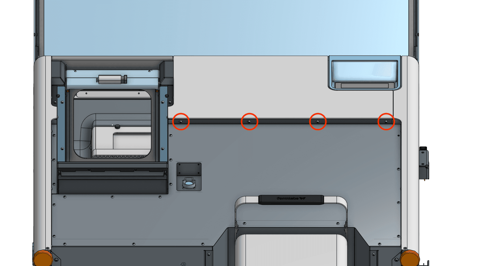
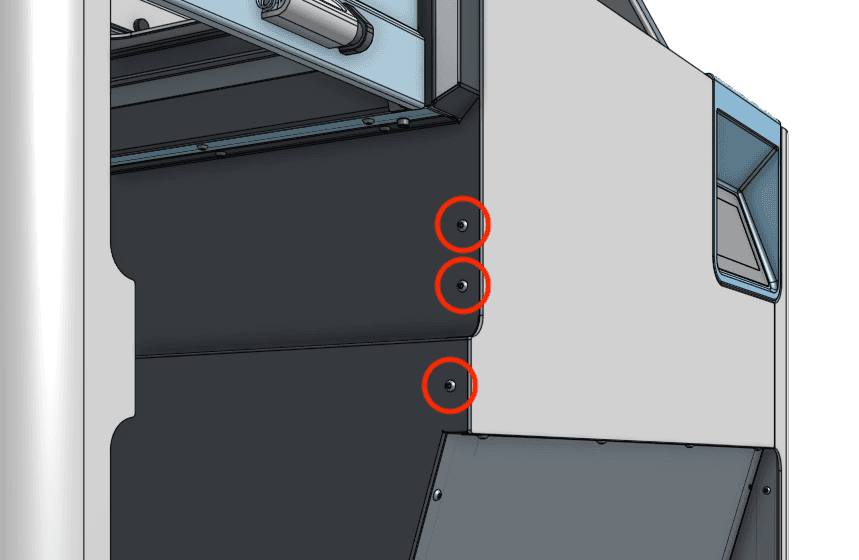
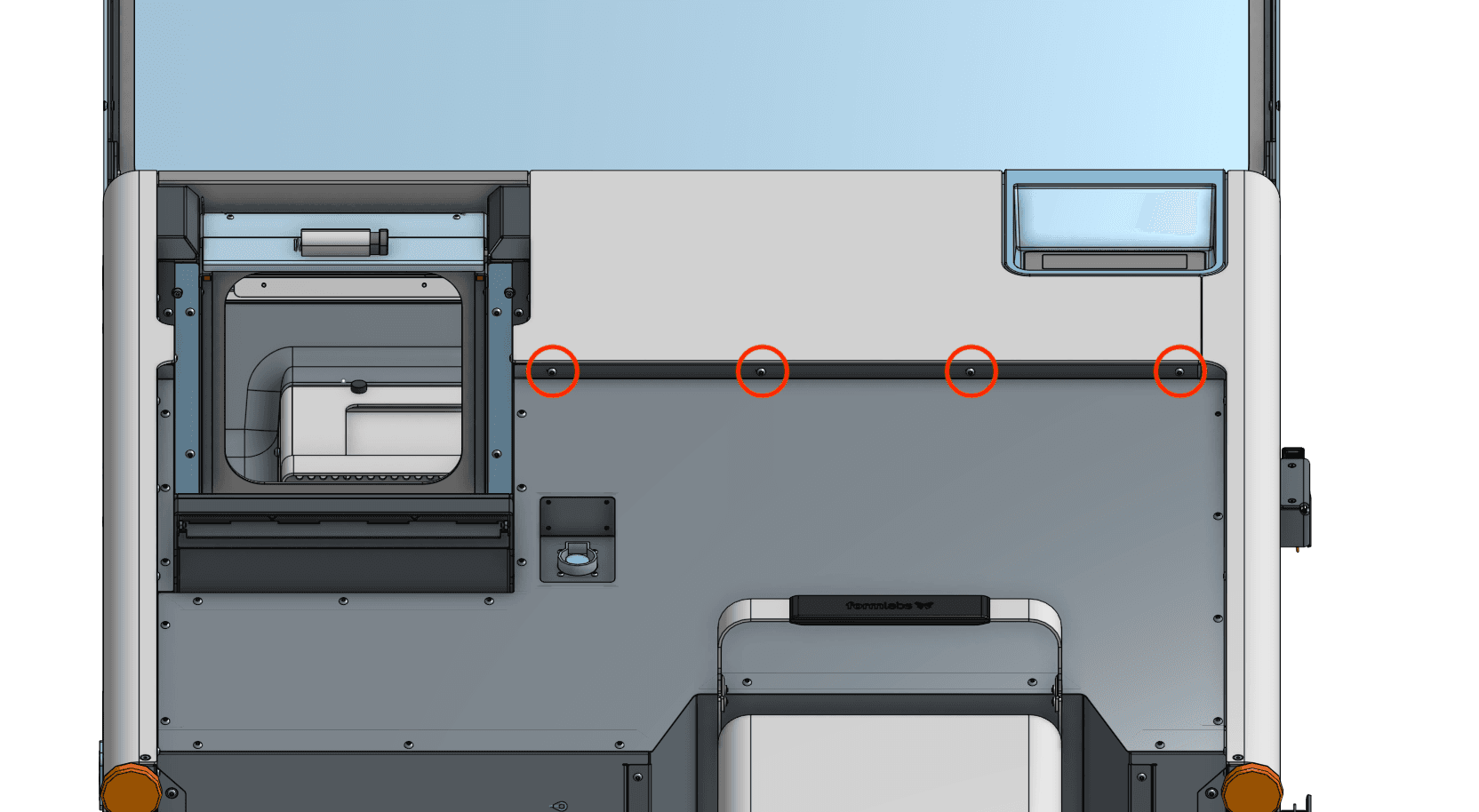
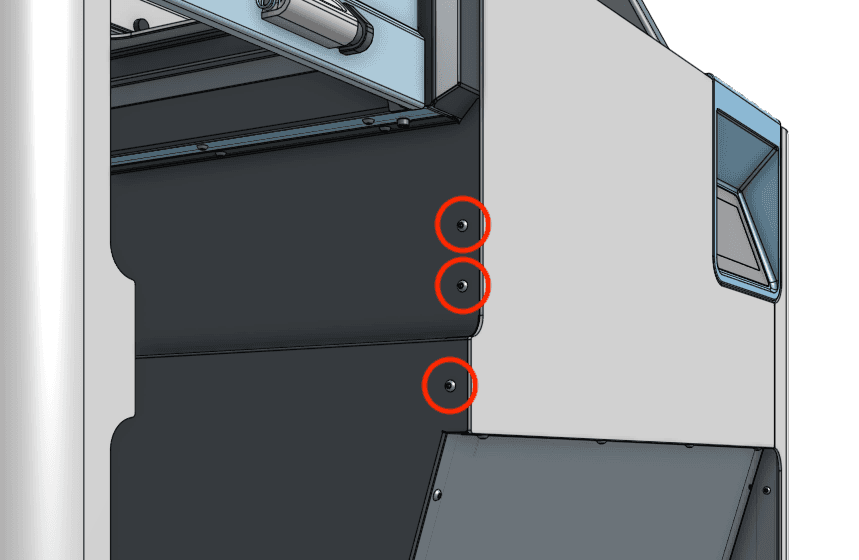
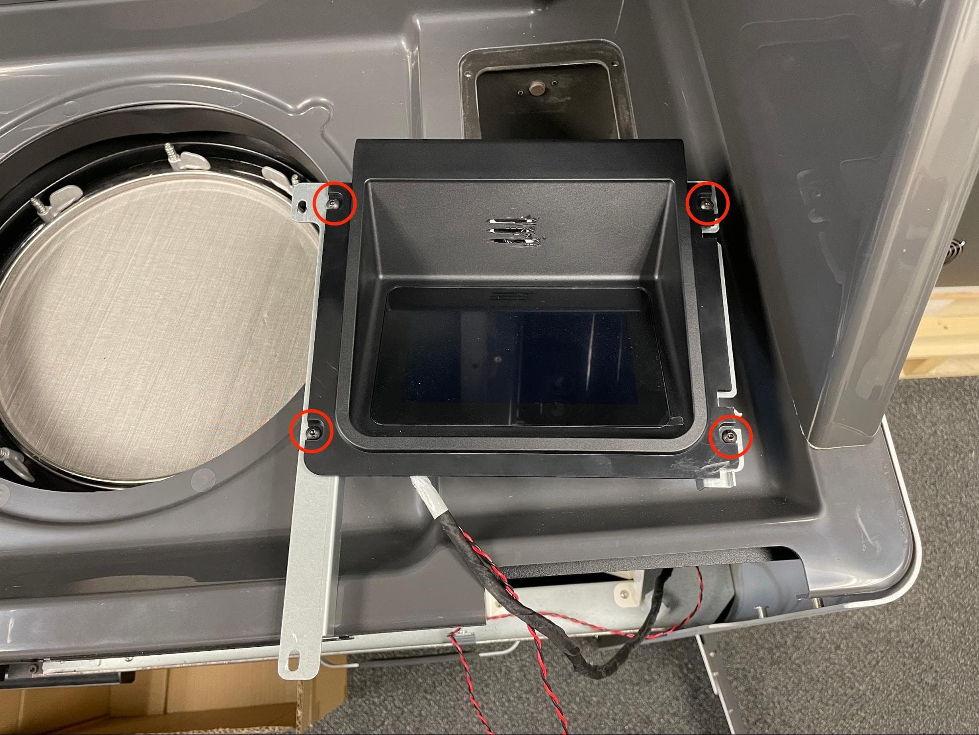
Using a 2.5 mm hex driver, loosen and remove the four black 8.0 mm M4 button screws underneath the upper front enclosure panel lip. Remove the three black 8.0 mm M4 button screws from the left-hand side of the same panel. Set the screws aside.

Step 2: Remove the upper front enclosure panel

Slide the panel downwards to remove it from the Fuse Sift. Set the upper front enclosure panel aside.

Removing the lower front enclosure panel

Overview: Remove the lower front enclosure panel to access the front of the mixer assembly.

Step 1: Unscrew the lower front enclosure panel mounting screws

Remove the lower front enclosure panel

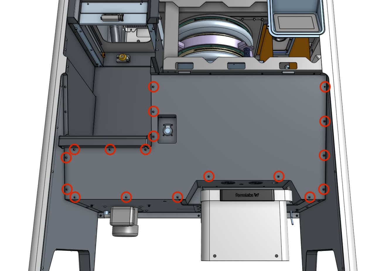
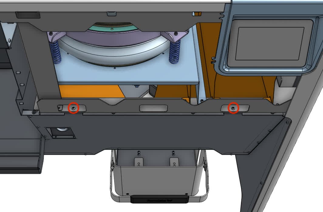
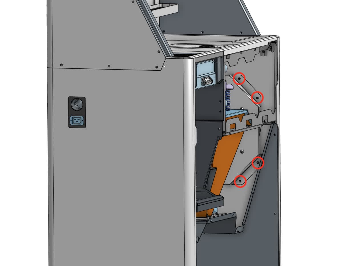
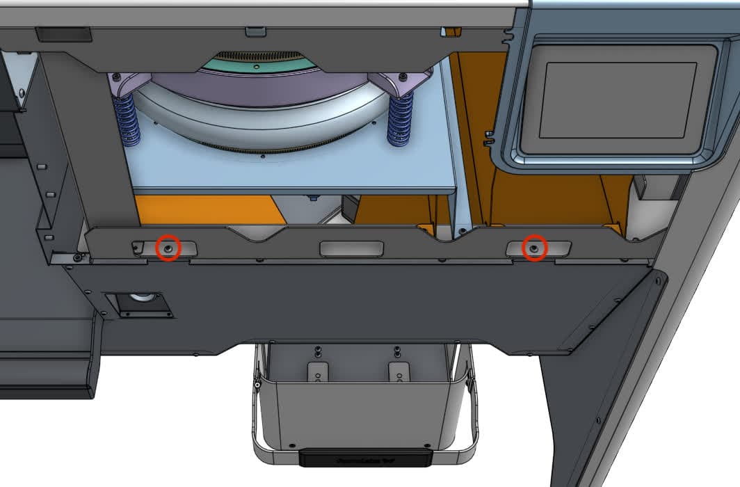
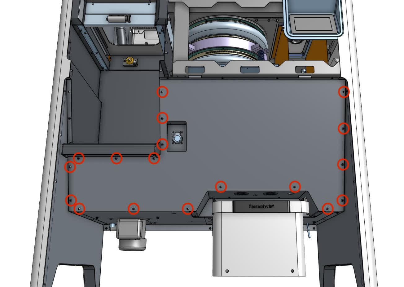
Using a 2.5 mm hex driver, loosen and remove the 18 black 8.0 mm M4 button head screws securing the lower front enclosure panel to the Fuse Sift. Remove the two chrome 8.0 mm M4 button screws holding the top of the lower panel to the inner frame. Hold the botton of the panel with one hand has you remove these screws to keep it from falling. Set all 20 screws aside.

Step 2: Remove the lower front enclosure panel.

Separate the lower front enclosure panel from the Fuse Sift. Set the panel aside.

Removing the display assembly

Overview: Disconnect and remove the display assembly to better access the mixer assembly.

Notice:

The Fuse Sift contains sensitive electronic components. Ground yourself before touching any electronics in the device by using an antistatic wrist band.

Step 1: Unscrew the display assembly frame mounting screws

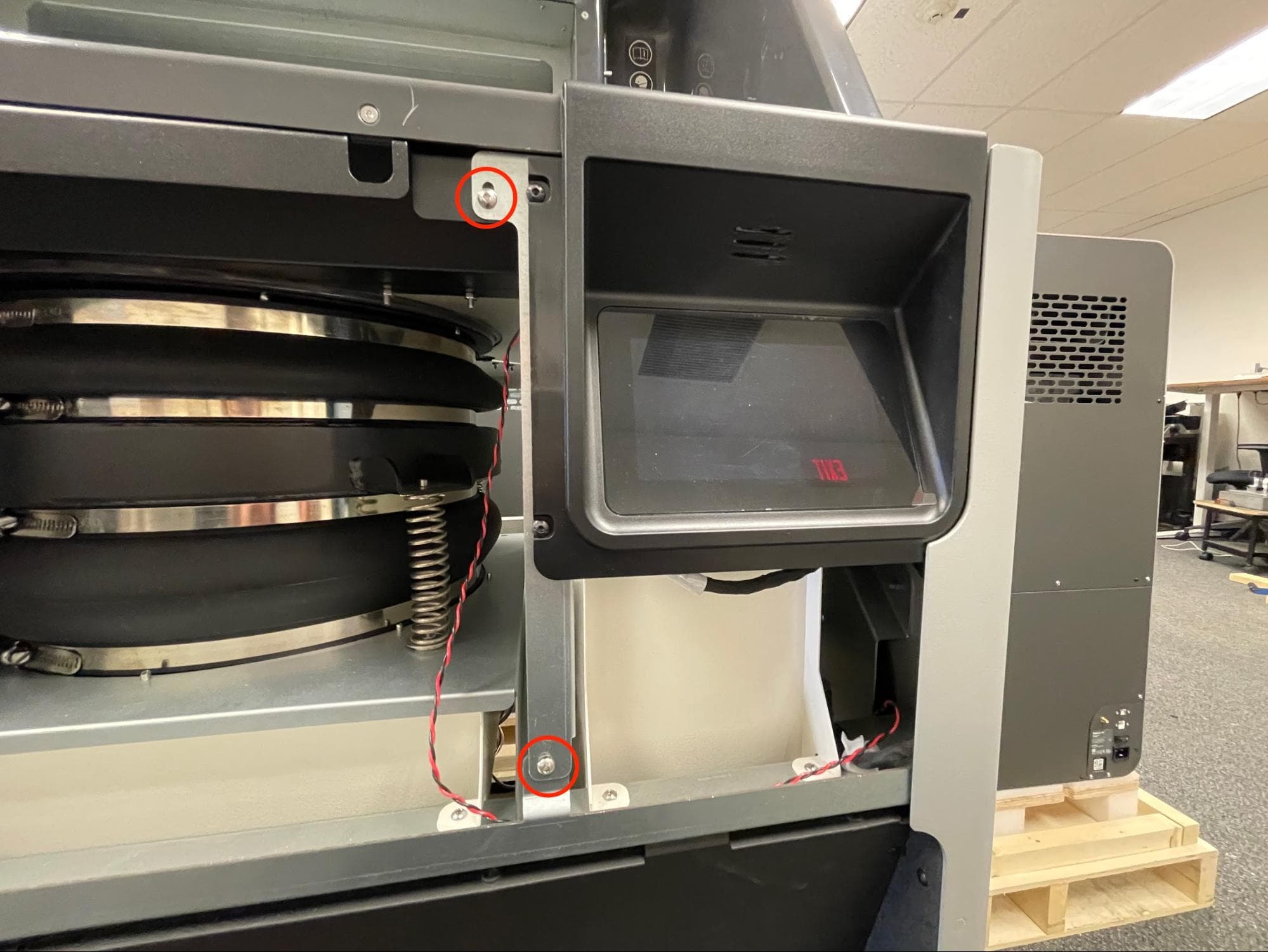
The display assembly is mounted to a frame that is then secured to the Fuse Sift. Using a 2.5 mm hex driver, loosen and remove the two chrome 8.0 mm M4 button screws securing the display assembly frame to the front of the Fuse Sift. Set the screws aside.

Remove the original display assembly

Step 2: Separate the display assembly and frame from the Fuse Sift

Remove the original display assembly

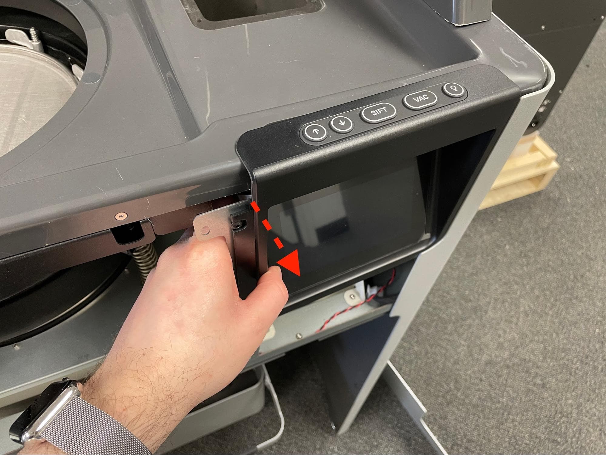
Gently pull the left side of the display assembly outward, then to the left. Do not pull sharply on the display assembly, as it is still connected to the Fuse Sift via a cable.

Step 3: Separate the display assembly cable from its clamp

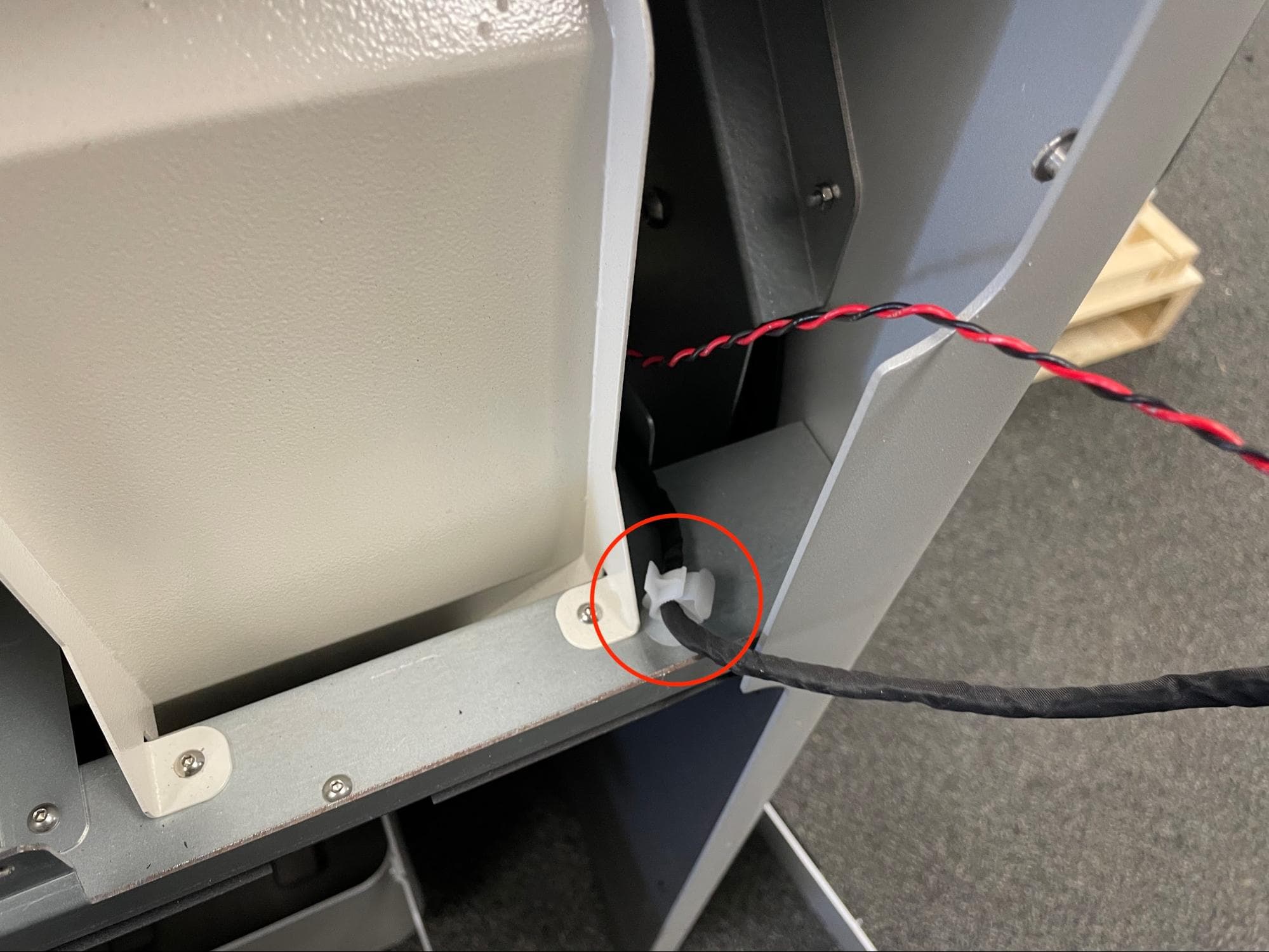
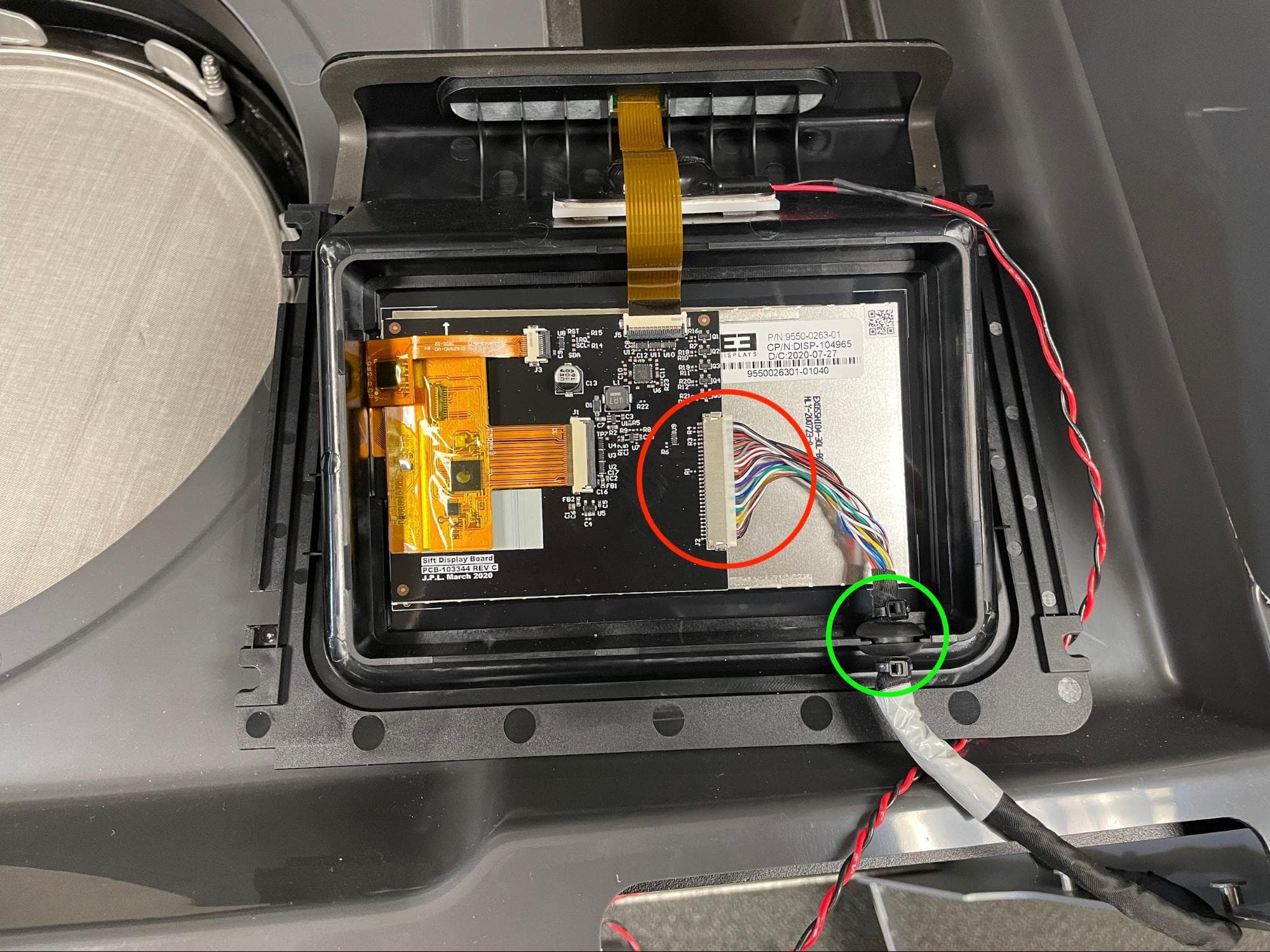
Unlock the cable clamp holding the display cable.

Remove the original display assembly

Step 4: Separate the display assembly from its frame

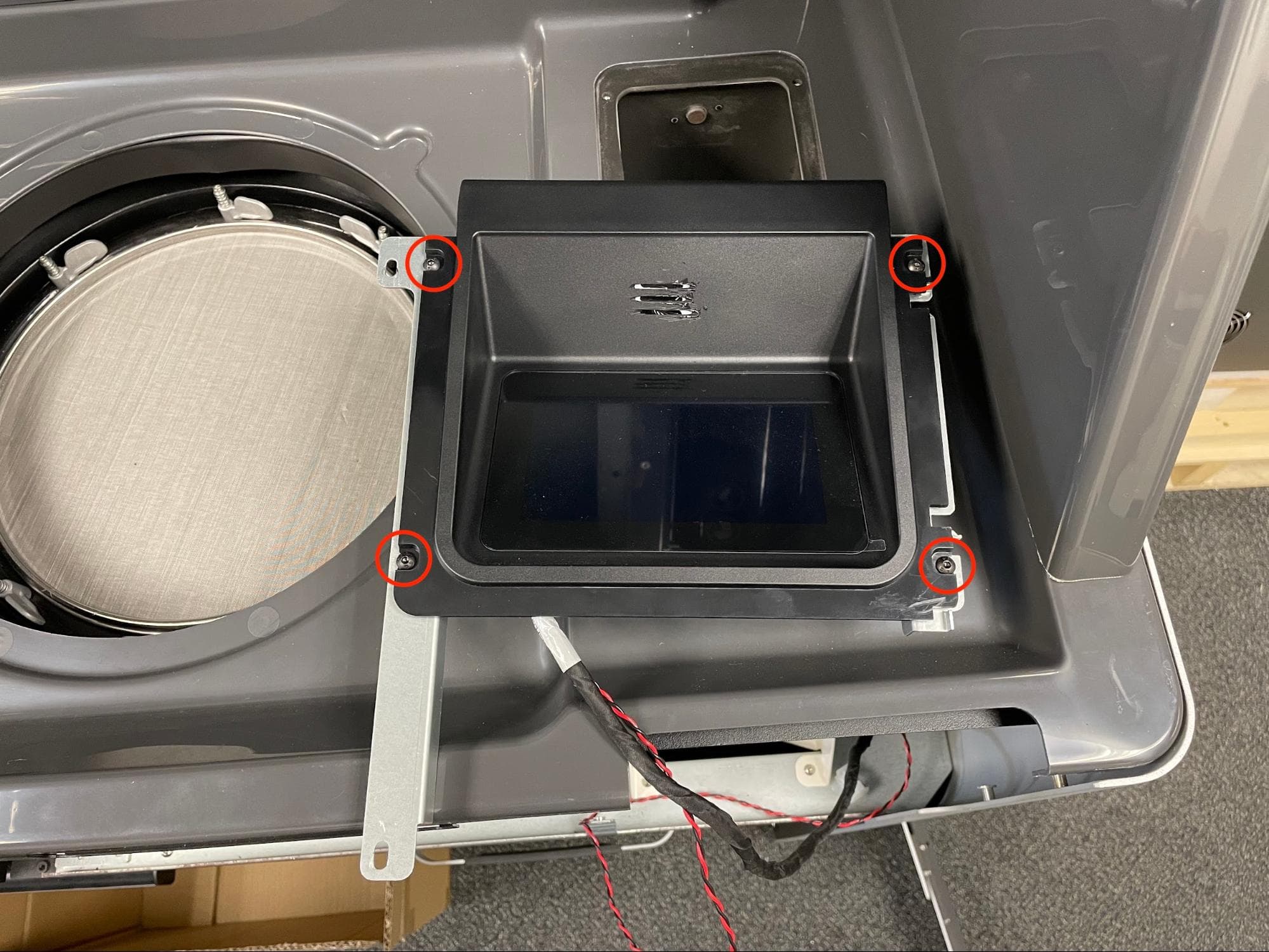
Place the display assembly in the workspace with the screen side facing up. Using a 2.5 mm hex driver, loosen and remove the four black 7.0 mm M4 button screws holding the metal frame to the display assembly. Set the frame and the screws aside.

Remove the original display assembly

Step 5: Disconnect the display cable from the display assembly

Turn the display assembly over and locate the display cable connector. Carefully disconnect the cable from the original display assembly, then separate the rubber grommet holding the cable from the display assembly. Set the display assembly aside for disposal with electronic waste.

If you are only replacing the display assembly, skip to Installing the replacement display assembly. Otherwise, continue.

Remove the original display assembly

Removing the rear enclosure panel

Overview: Separate the rear enclosure panel from the Fuse Sift in order to access the back of the mixer assembly.

Step 1: Unscrew the rear enclosure panel mounting screws

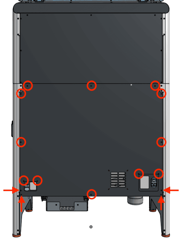
Use a 2.5 mm hex driver to remove the 16 black 8.0 mm M4 screws securing the rear panel to the Fuse Sift. Set the screws aside.

Step 2: Remove the rear closure panel

Separate the rear enclosure panel from the Fuse Sift and set it aside.

Remove the rear enclosure panel

Removing the mixer assembly

Overview: Disconnect and remove the original mixer assembly.

Step 1: Disconnect the mixer assembly cables

Remove the original mixer assembly

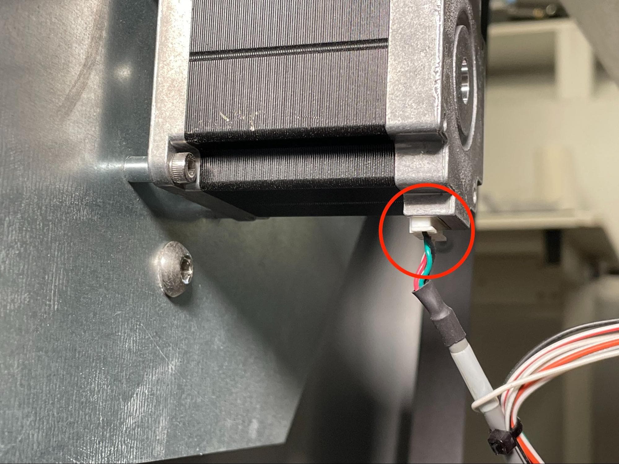
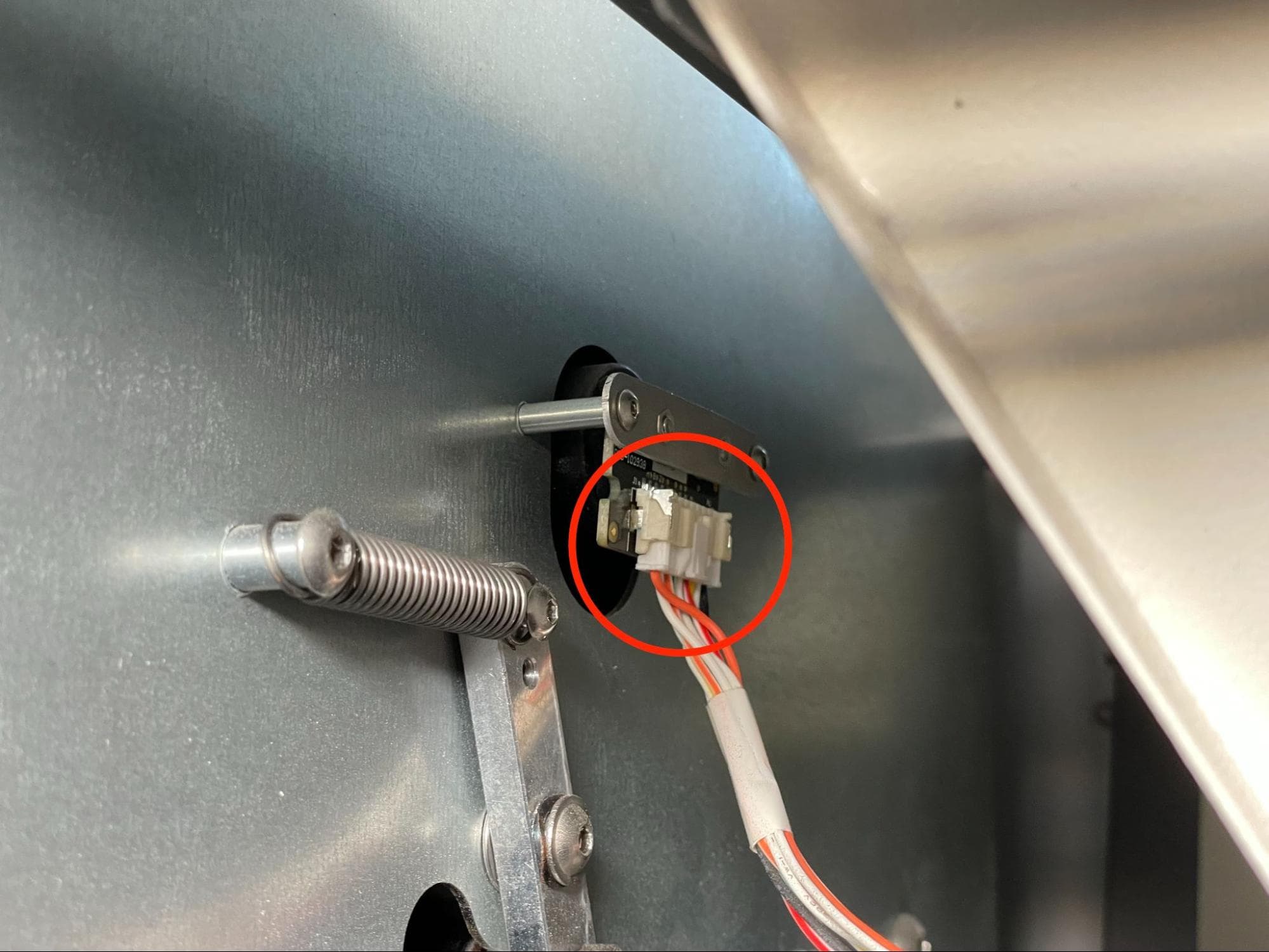
Locate the inner mixer assembly components on the right side of the Fuse Sift. Disconnect the mixer motor cable and mixer encoder cable. The mixer encoder cable has a locking tab that must be squeezed before it can be unplugged. In both cases, pull on the plastic connectors and not the wires themselves.

Step 2: Separate the mixer encoder cable harness from the mixer

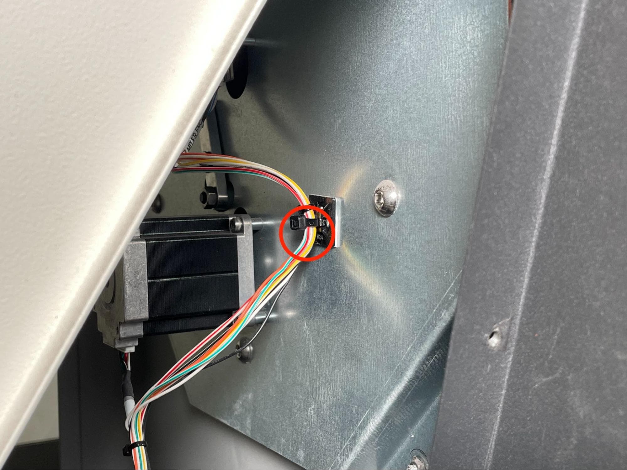
Use a pair of flush cutters to cut the zip tie securing the encoder cable harness to the mixer assembly.

Remove the original mixer assembly

Step 3: Unscrew the mixer assembly mounting screws

Remove the original mixer assembly

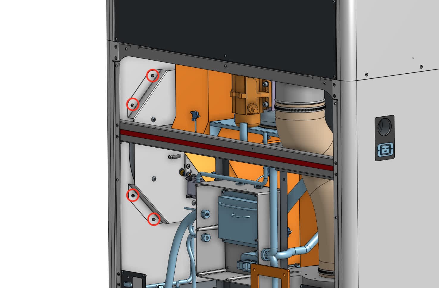
Using a 7.0 mm compact socket or box wrench, loosen and remove the eight chrome M4 nuts securing the mixer assembly to the Fuse Sift. Set the nuts aside

Step 4: Remove the mixer assembly

Remove the original mixer assembly

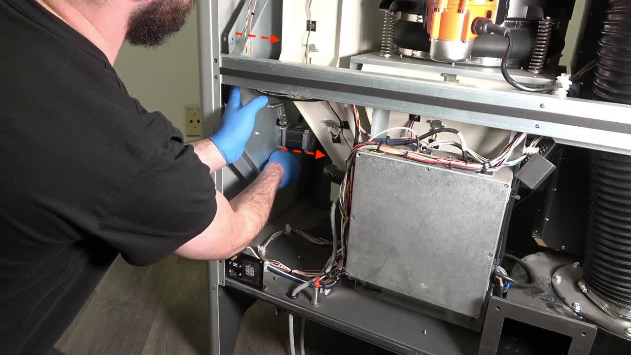
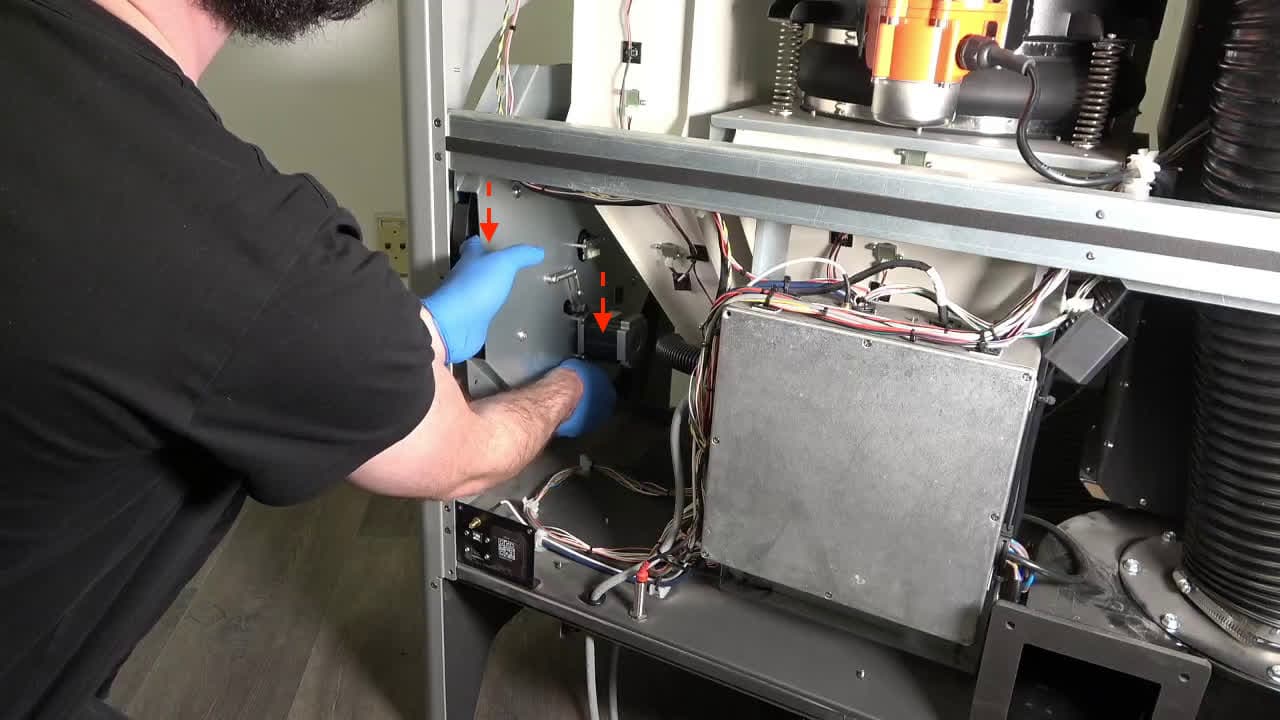
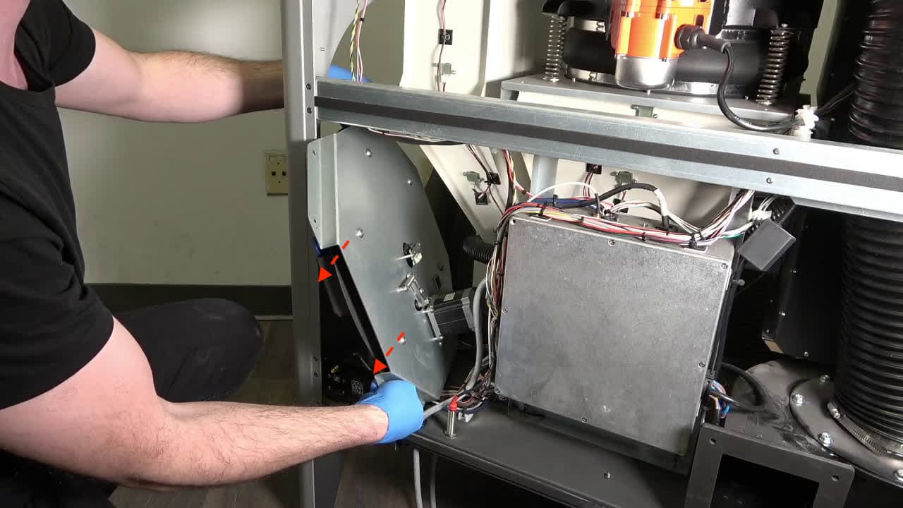
From the back of the machine, grip the mixer assembly frame. Pull the mixer assembly towards the center of the machine to free it from the studs it rests on. Lower the mixer below the mid-brace running horizontally across the machine. Tilt the mixer assembly to clear the IO panel at the lower-left corner of the Fuse Sift, then guide the assembly out through the rear of the machine. Set the mixer assembly aside for disposal with electronic waste.

Installing the replacement mixer assembly

Overview: Mount, secure, and connect the replacement mixer assembly.

Step 1: Check the new mixer assembly

Install the new mixer assembly

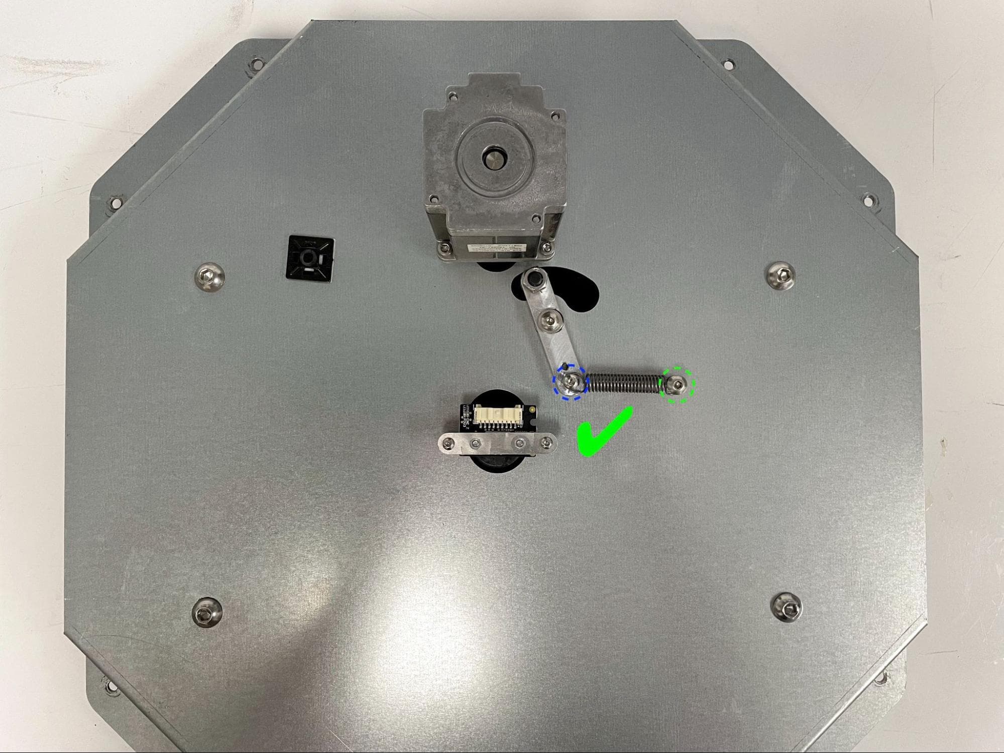
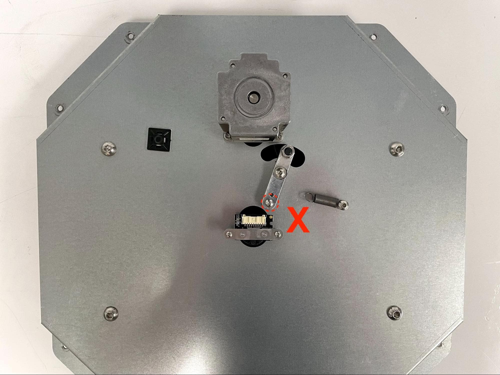
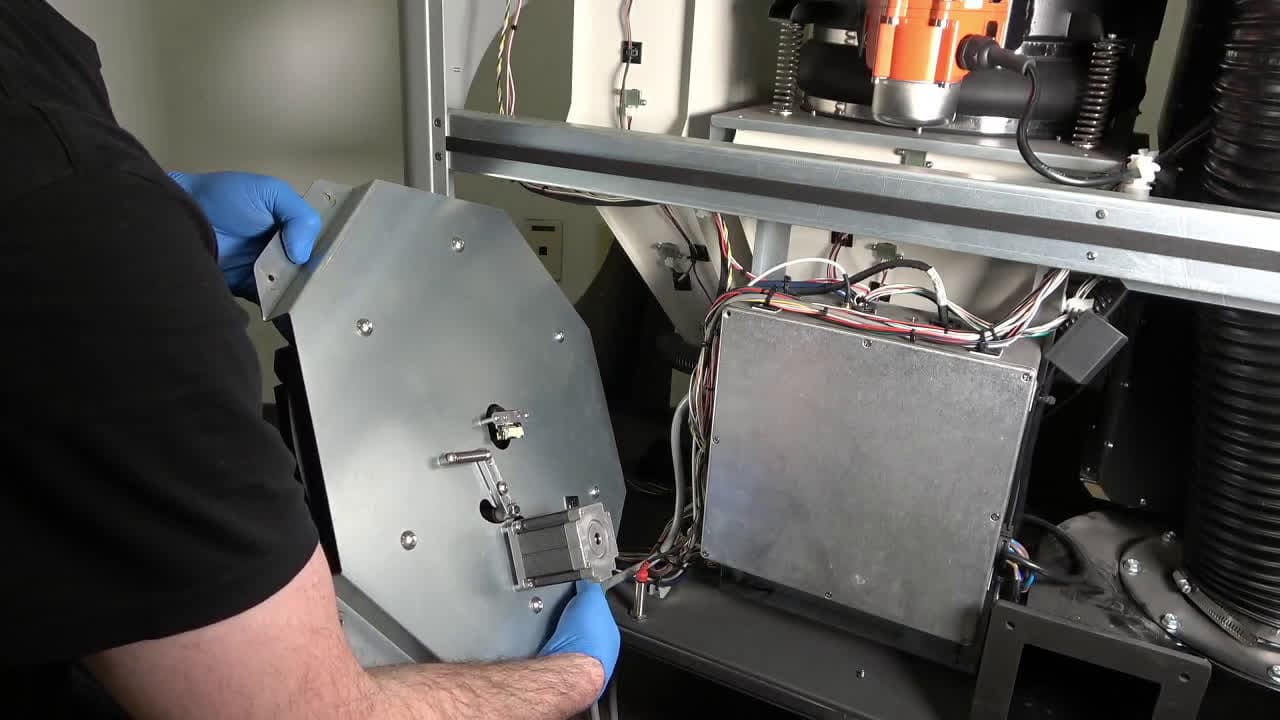
Remove the new mixer assembly from its packaging and check the following:

  • The mixer belt’s tensioner spring is secured to both the back plate and the tensioning arm
  • The mixer clips spring back into place after being depressed

Step 2: Mount the mixer assembly

Install the new mixer assembly

Pick up the mixer assembly by its frame, oriented so that the motor is below the encoder. Tilt the mixer assembly to clear the IO panel, then guide the assembly into the back of the machine. Gently lift the mixer assembly up and align it with the eight studs on the inner wall of the Fuse Sift, then push it into place so that all four flanges are flush with the inner wall of the machine.

Step 3: Secure the mixer assembly

Install the new mixer assembly

Apply a small dab of Loctite 243 or equivalent threadlocker to the threads of all eight studs. Thread one chrome M4 nut onto each of the eight studs, then use a 7.0 mm compact socket or box wrench to tighten until snug.

Step 4: Connect the mixer assembly cables

Reconnect the motor and encoder cables. Ensure that the encoder cable locking tab clicks into place.

Step 5: Route the encoder cable harness

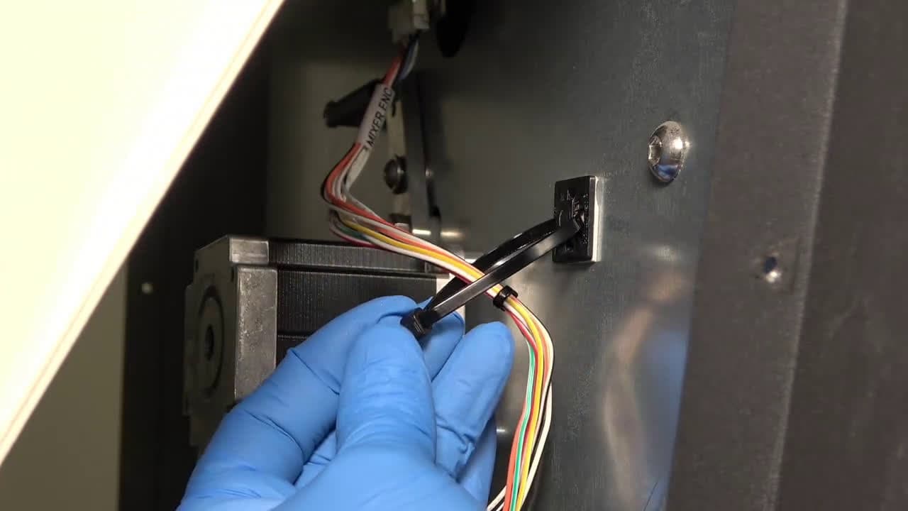
Feed a nylon zip tie through the anchor on the new mixer assembly, then secure it around the encoder cable harness. Use a pair of flush cutters to cut away the excess zip tie.

Install the new mixer assembly

Reinstalling the rear enclosure panel

Overview: Mount and secure the rear enclosure panel after installing the new display assembly and cable.

Step 1: Prepare the rear panel retention screws

Apply a small amount of Loctite 243 or other similar threadlocker to each of the 16 black 8.0 mm M4 button screws that secure the rear panel to the Fuse Sift.

Step 2: Mount the rear panel

Mount the rear panel onto the Fuse Sift.

Step 3: Secure the rear panel

Thread one 8.0 mm M4 button screw into each of the 16 screw holes in the rear panel. Use a 2.5 mm hex driver to tighten until snug.

Fuse sift rear enclosure panel

Tip:

Start with the top three screws to hold the panel in place while you thread and tighten the remaining screws.

Reinstalling the lower front enclosure panel

Overview: Mount and secure the lower front enclosure panel after installing the new mixer assembly.

Step 1: Mount the lower front enclosure panel

Mount the lower front enclosure panel onto the Fuse Sift. Align the 20 screw holes in the panel with the corresponding screw holes in the machine.

Step 2: Secure the lower front enclosure panel

Replace the lower front enclosure panel

Apply a small dab of Loctite 243 or equivalent threadlocker to each of the 20 8.0 mm M4 button head screws that secure the lower front enclosure panel to the Fuse Sift. Thread one chrome screw into both of the screw holes on the top of the panel. Thread one black screw into each of the 18 screw holes in the front of the panel. Using a 2.5 mm hex driver, tighten all 20 screws until snug.

Reinstalling the display assembly

Overview: Mount, secure, and connect the display assembly.

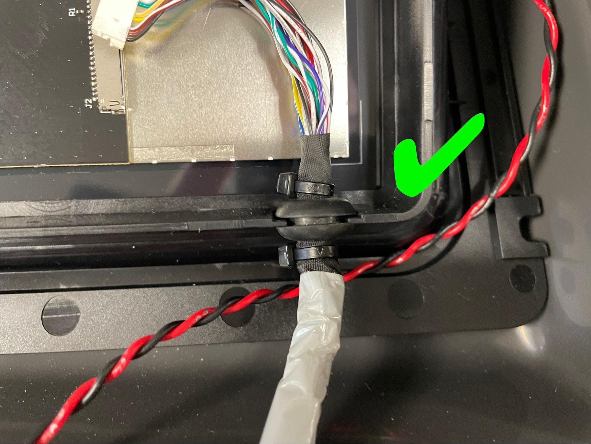
Step 1: Mount the display cable grommet to the display assembly

Install the new display assembly

Seat the groove in the display cable’s rubber grommet onto the cutout in the display assembly.

Step 2: Connect the display cable to the display assembly

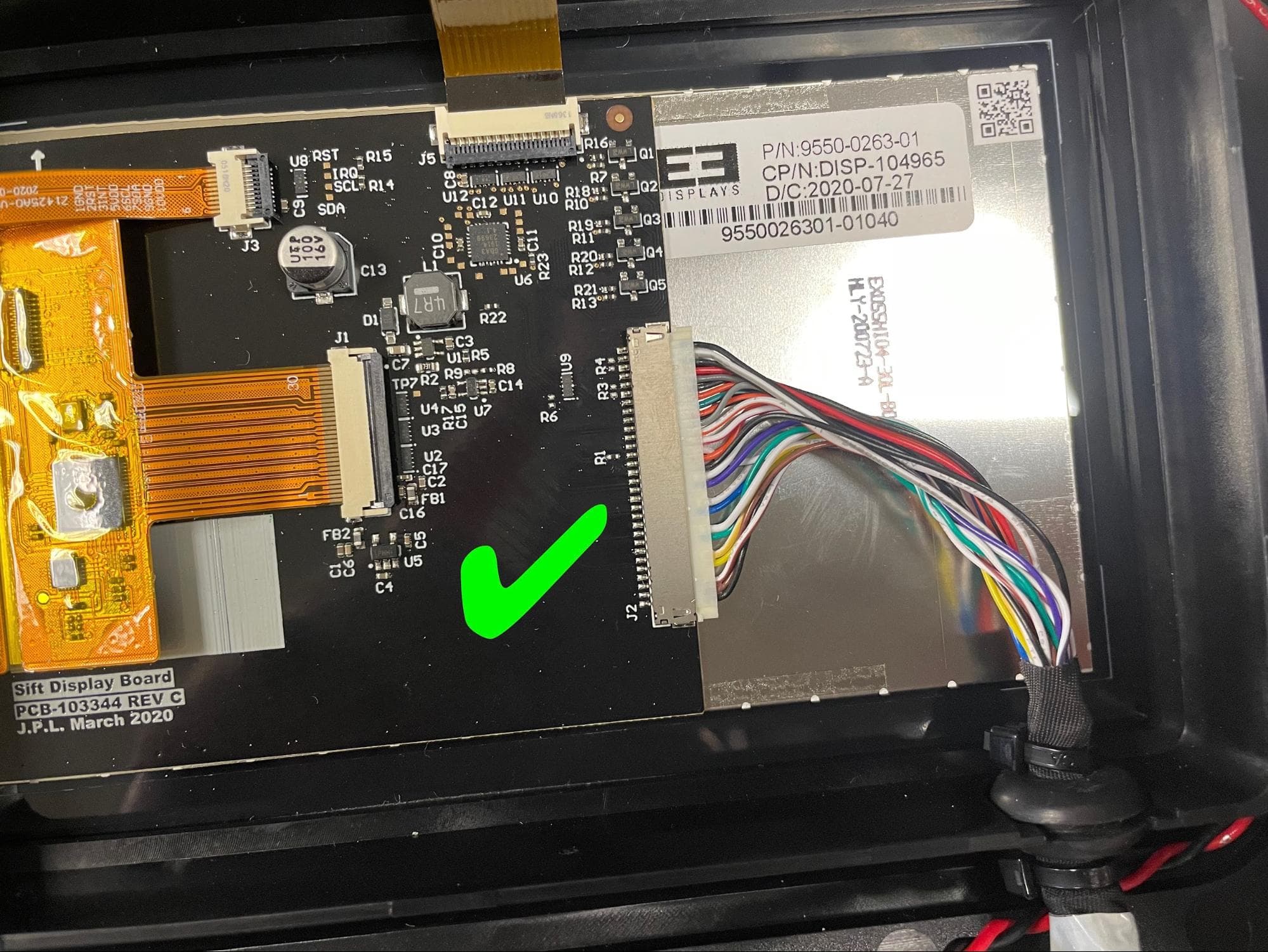
Plug the display cable connector into the display assembly.

Install the new display assembly

Step 3: Mount the display assembly to its frame

Place the display assembly on its metal frame, with the long edge of the frame on the left. Align the four screw holes in the display assembly with the corresponding screw holes in the frame.

Step 4: Secure the display assembly to its frame

Apply a small dab of Loctite 243 or equivalent threadlocker to each of the four black 8.0 mm M4 button head screws that secure the display assembly to its frame. Thread one screw into each of the four screw holes in the display assembly. Using a 2.5 mm hex driver, tighten until snug.

Install the new display assembly

Step 4: Route the display cable

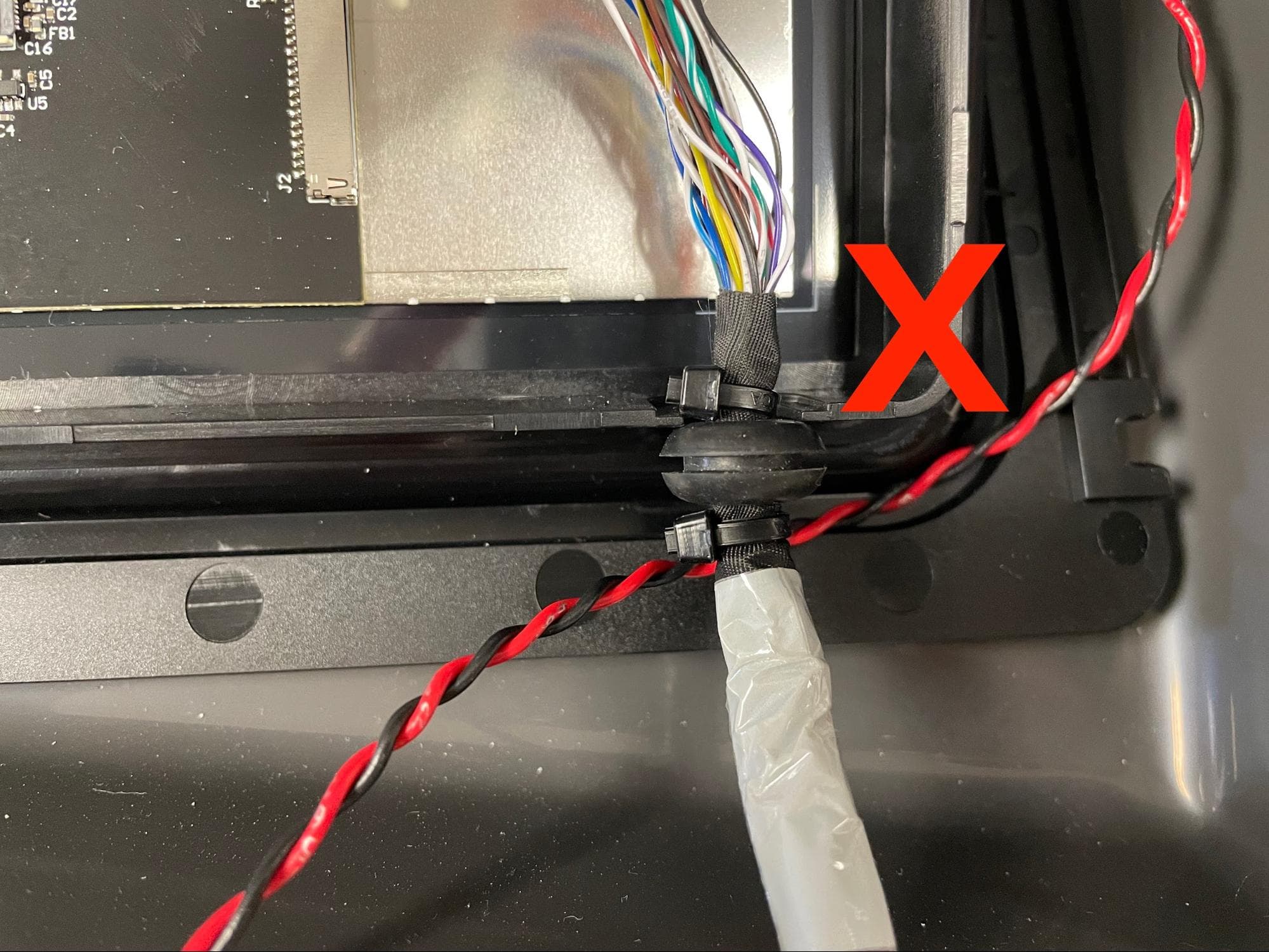
Feed the display cable back into the cable clamp below the display assembly, then reengage the lock.

Step 5: Mount the display assembly

Install the new display assembly

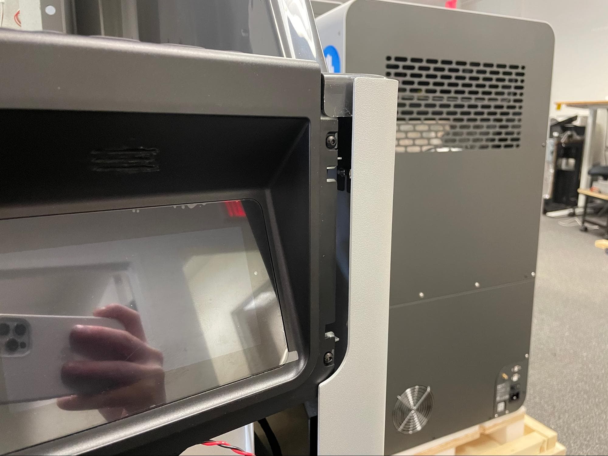
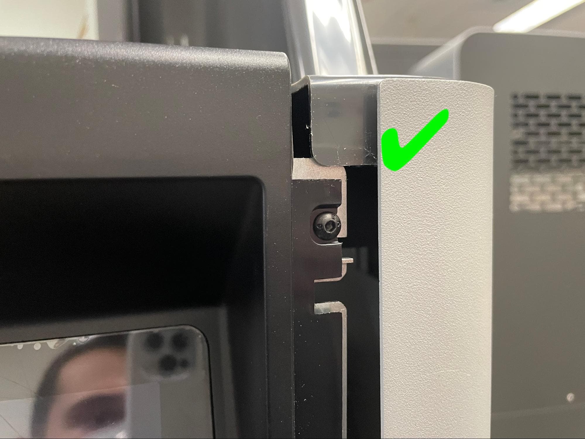
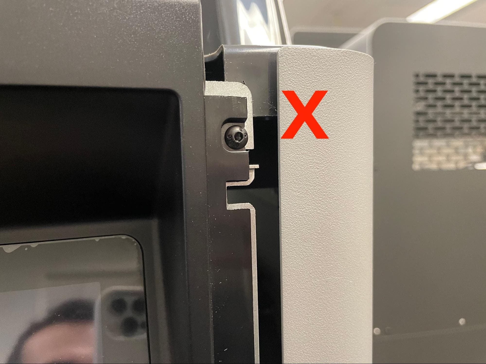
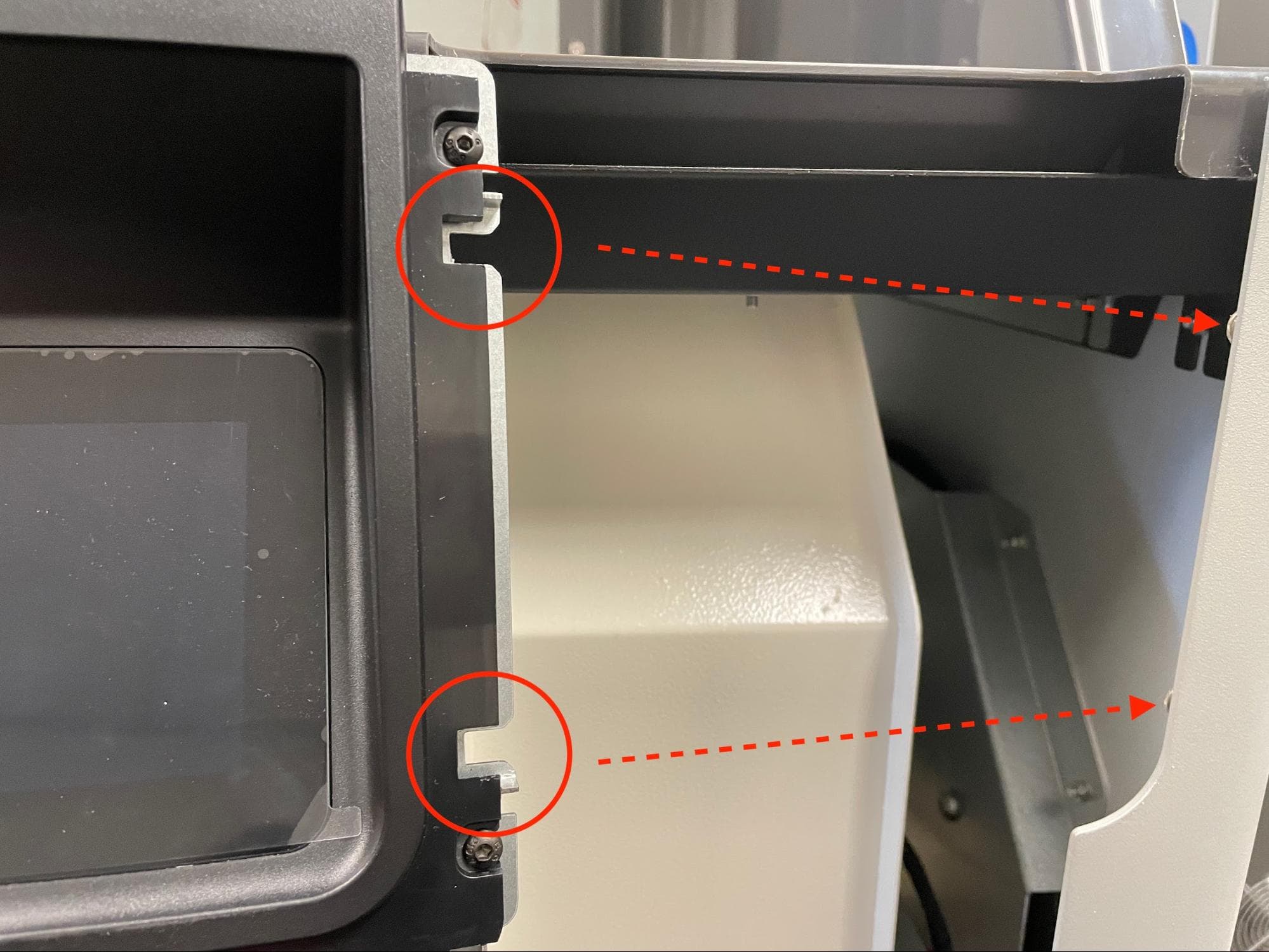
Locate the two slots on the right-hand side of the display assembly, as well as the corresponding posts behind the adjacent panel. Slide the slots onto the posts, then push the left side of the display assembly towards the Fuse Sift to seat it into place.

Install the new display assembly

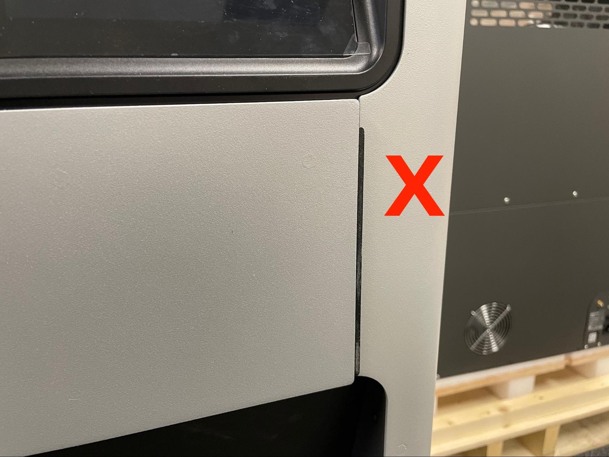
Note that the metal display assembly frame needs to be behind the grey plastic of the adjacent panel in order for the display assembly to properly slot into place.

Step 6: Secure the display assembly

Apply a small dab of Loctite 243 or similar threadlocker to the threads of the two chrome 8.0 mm M4 screws that secure the display assembly to the Fuse Sift. Thread one screw into both of the two screw holes in the left side of the display assembly frame. Using a 2.5 mm hex driver, tighten until snug.

Pull any slack in the display cable into the Fuse Sift from the back.

Install the new display assembly

Reinstalling the upper front enclosure panel

Overview: After reinstalling the display assembly, reinstall the upper front enclosure panel.

Step 1: Align the upper front enclosure panel

Replace the upper front enclosure panel

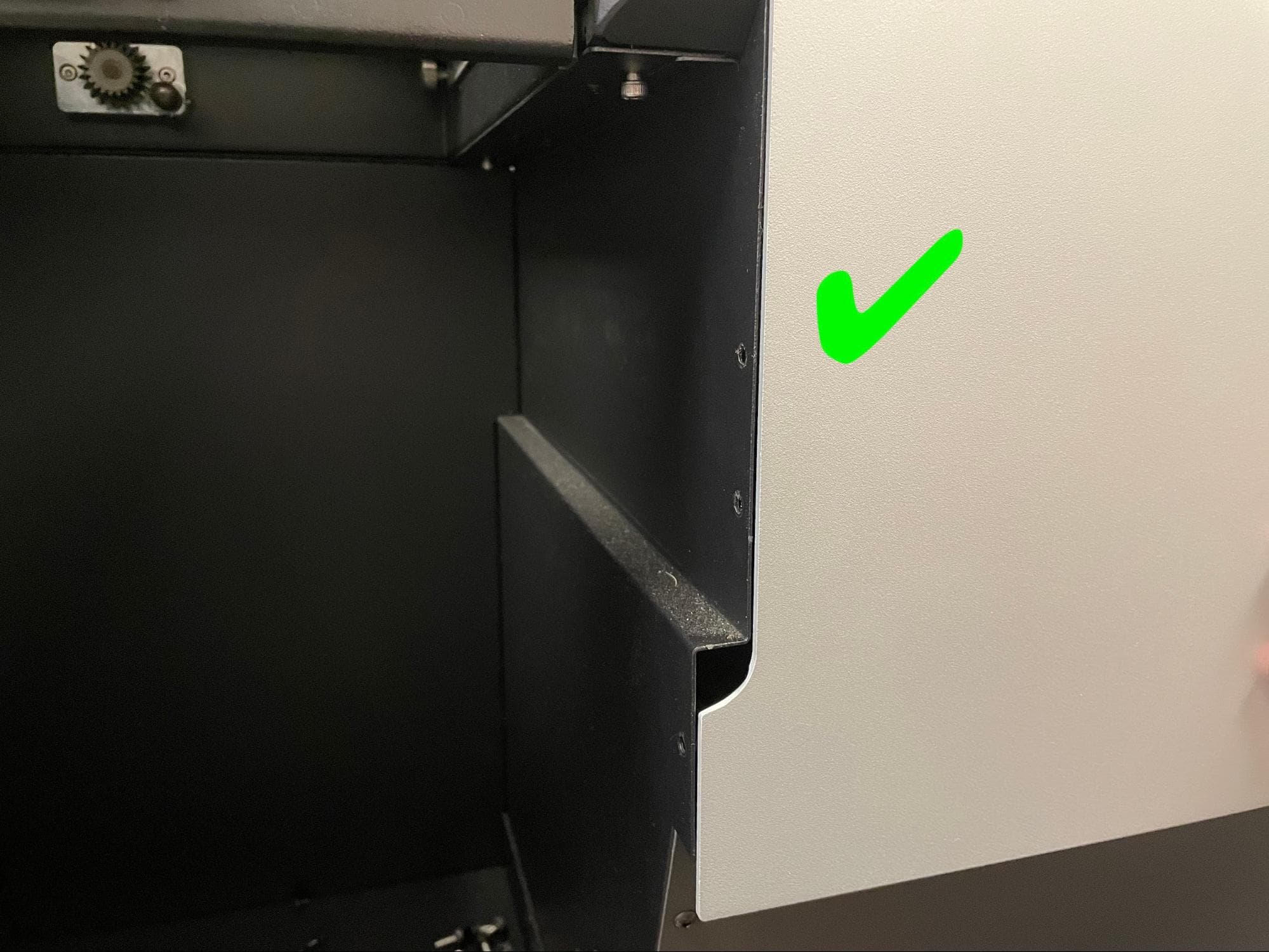
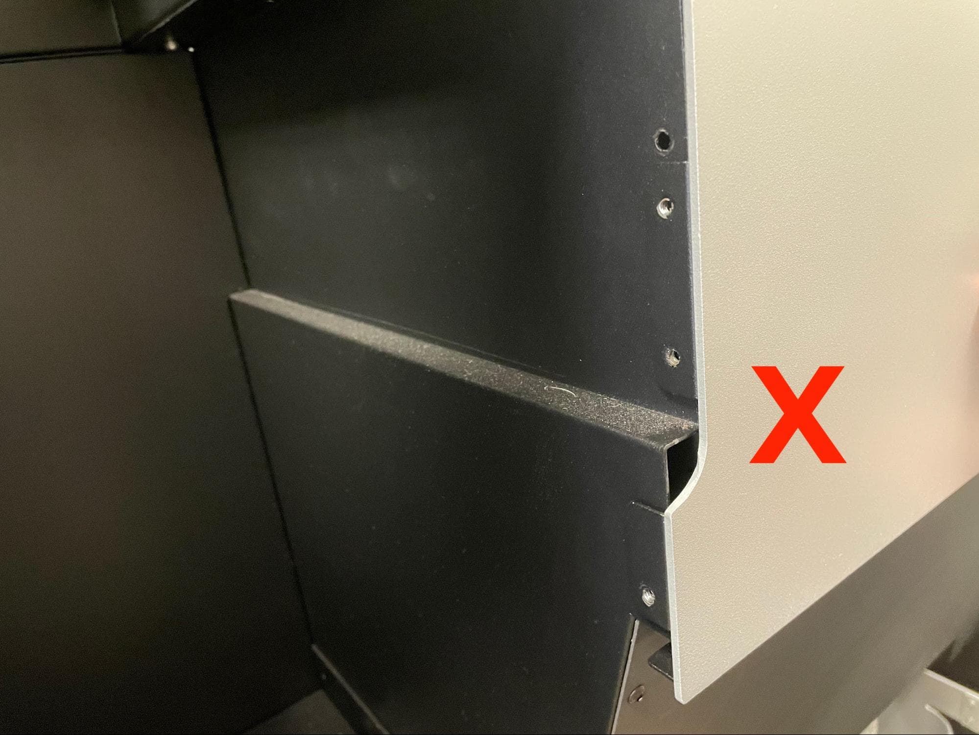
Align the upper front enclosure panel with the so that the black tab on the right-hand side of the panel and the two black flanges on the left-hand side of the panel are not visible. Start by aligning the smaller tab on the right first.

Step 2: Mount the upper front enclosure panel

Slide the panel upwards until it locks into place. Note that the panel can still fall down if knocked or hit.

Replace the upper front enclosure panel

Step 3: Secure the upper front enclosure panel

Replace the upper front enclosure panel

Apply a small dab of Loctite 243 or equivalent threadlocker to each of the seven black 8.0 mm M4 button head screws that secure the upper front enclosure panel to the Fuse Sift. Thread one of the screws into each of the seven screw holes in the panel. Using a 2.5 mm hex driver, tighten the screws until snug.

Finalizing the repair

Overview: After installing the new mixer assembly, power on the Fuse Sift and calibrate the replacement part.

Step 1: Power on the Fuse Sift

Reconnect the Fuse Sift to its power source. Flip the power switch to the ON position.

Step 2: Calibrate the mixer

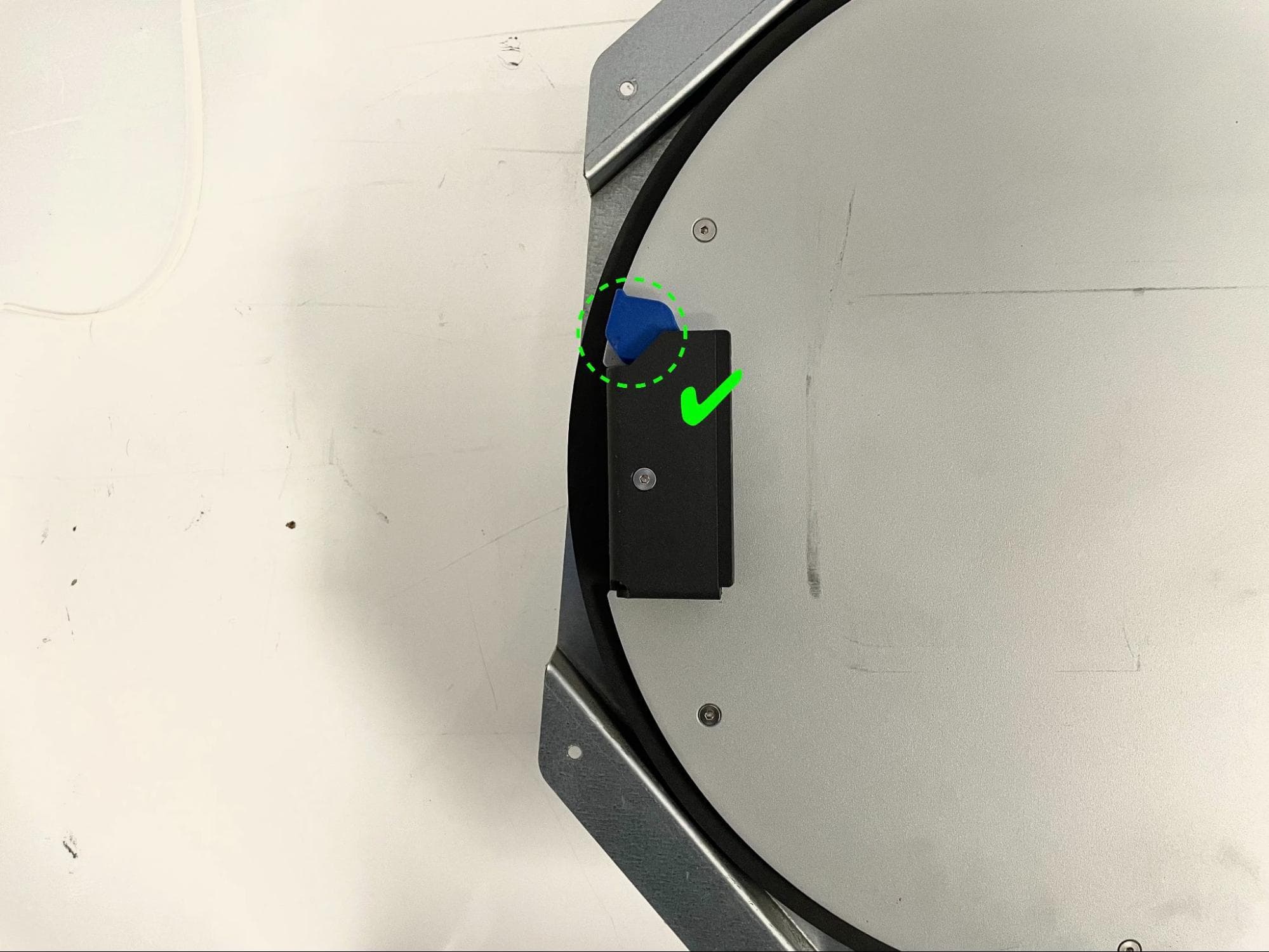
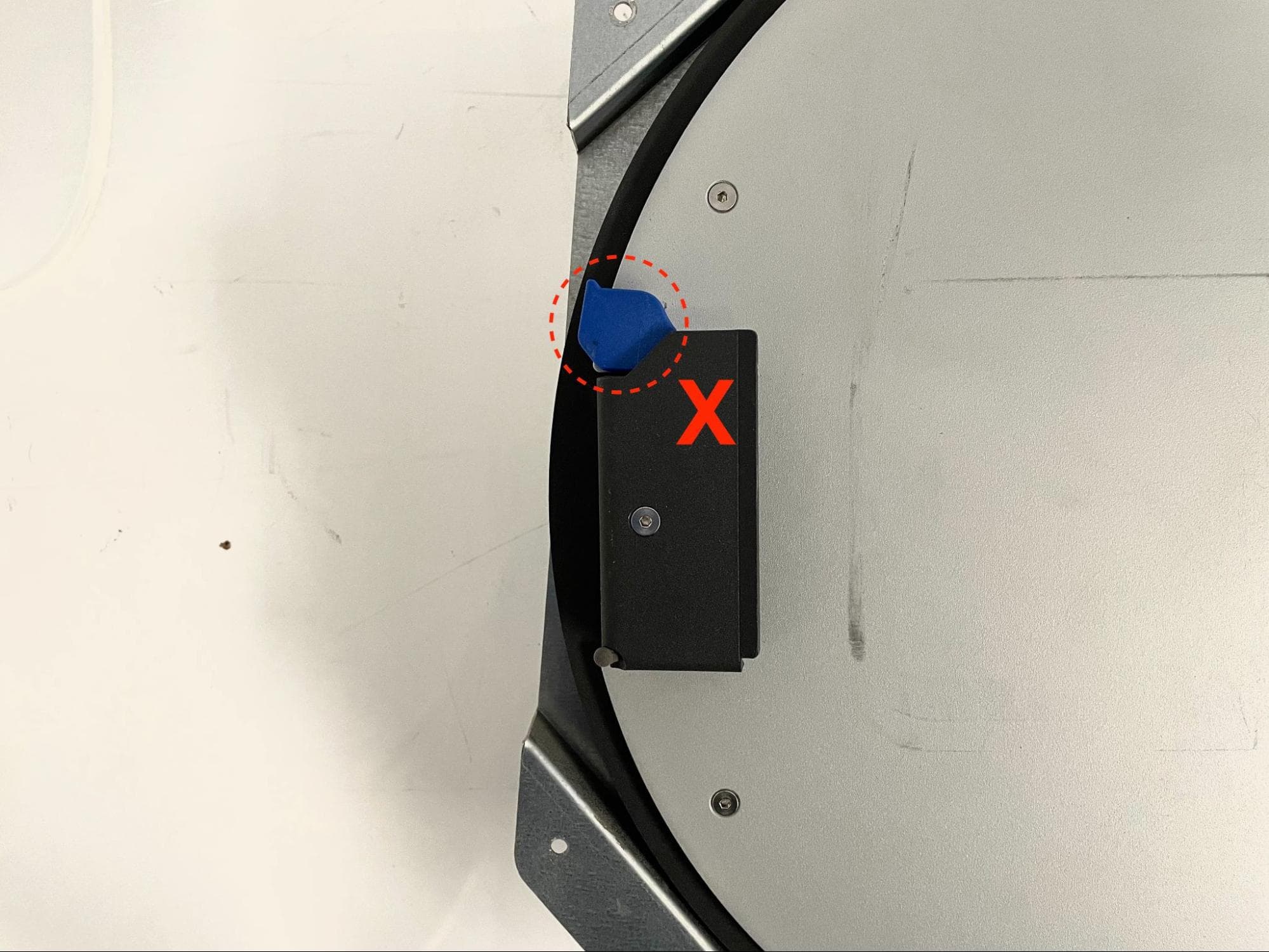
Ensure that the mixer is oriented so that the blue plastic clips are pointing upwards. Rotate the mixer if necessary. On the touchscreen, tap Maintenance > Calibrate Mixer. Follow the instructions on the UI to complete the calibration procedure.

For more details, see our support article on calibrating the Fuse Sift mixer.

Step 3: Test the mixer calibration

Insert a powder cartridge into the mixer and start a mix cycle. If the mixer stops with the cartridge in a horizontal position at the end of the cycle, the calibration was successful. If it stops at an angle, perform the mixer calibration procedure again.

If you encounter issues with the mixer calibration routine, contact Formlabs Support or your certified service provider.