
Required supplies:
Formlabs:
- Fuse 1 display assembly (RP-FS1-SN-01)
Third-party:
- 2.5 mm hex driver (flat-end)
- 3 mm hex driver (must have a 90º head)
- ESD-safe spudger (recommended) or ESD-safe tweezers
- Antistatic wrist band
- Flashlight (optional)

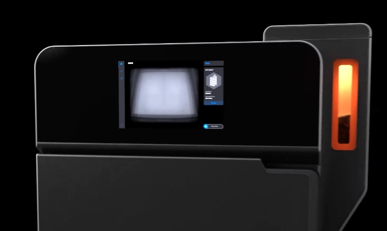
The Fuse 1 touchscreen is the primary means of interacting with and controlling the printer. A broken or malfunctioning touchscreen may prevent the printer from being used normally.
Use this guide to replace the display assembly on a Fuse 1 printer. To replace this component on a Fuse 1+ 30W printer, see Replacing the Fuse 1+ 30W display assembly.
Required supplies:
Formlabs:
Third-party:
Estimated time: 45–60 minutes
Danger:
Read and follow all safety instructions and warnings in the operator manual. Replacement with incorrect parts can lead to burns, shock, fire, or explosion. Dispose of all parts in accordance with local regulations.
Warning:
Do not perform this procedure if the printer was printing less than six hours prior. Failure to do so may result in serious burns. Allow the print enclosure to cool to room temperature before touching or inspecting any Fuse 1 components.
Preparing the workspace
Overview: Prepare the printer and a dust-free workspace for replacing the display assembly.
Notice:
Fuse 1 generation printers contain sensitive electronic components. Ground yourself before touching any electronics in the printer by using a grounding strap or touching a grounded piece of metal.
Step 1: Prepare the workspace
Clear a workspace around your printer. Ensure that the workspace is well-ventilated and free of dust.
Step 2: Unplug the printer
Disconnect the power cable before continuing with maintenance. Do not perform maintenance on the printer while it is connected to power. Wait five minutes after disconnecting the printer from power before proceeding.
Danger:
Performing maintenance on the printer while it is plugged in increases the risk of electric shock. Never remove the back panel of the printer while the printer is plugged in. Never reconnect the printer to power while the back panel is uninstalled.
Removing the top panel
Overview: Remove the top panel to access the interior of the printer.
Step 1: Remove the top panel screws
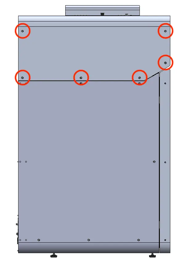
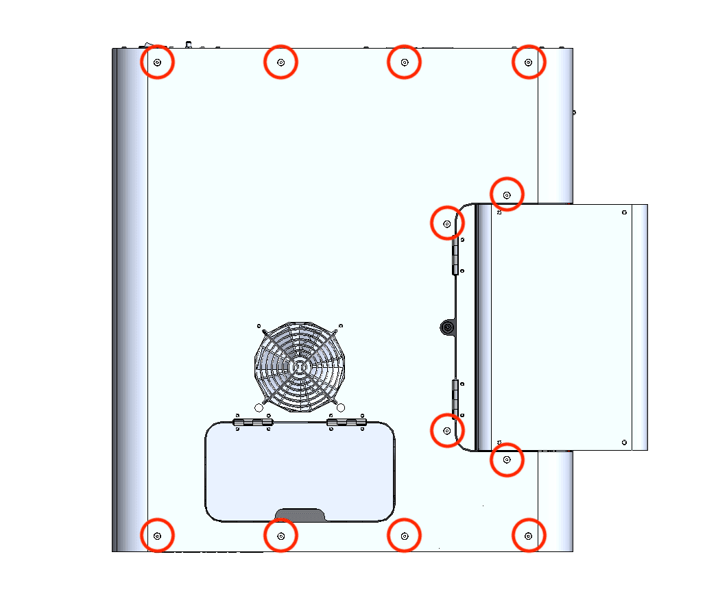
Using a 2.5 mm hex driver, remove the 26 6 mm M4 countersunk screws securing the top panel to the printer:
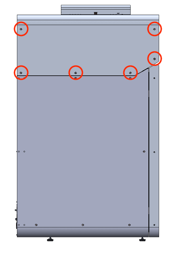
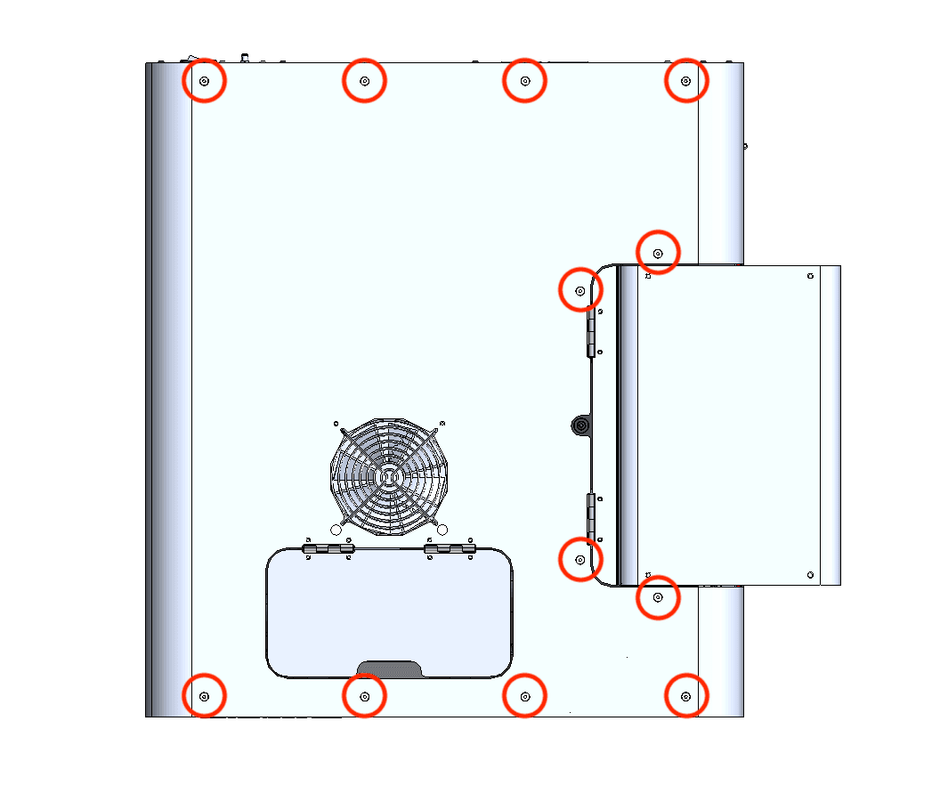
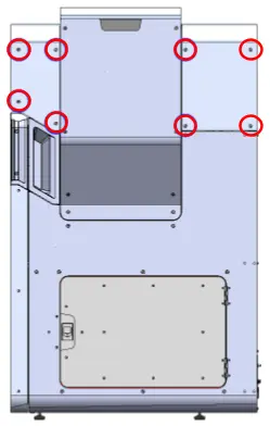
Set the screws aside.
Step 2: Remove the top panel
Lift the top panel off of the printer by grabbing the IR sensor door and the rear-most edge. Set the top panel aside.
Removing the upper cooling shroud
Overview: Remove the upper cooling shroud to access the display manel mounting screws.
Step 1: Remove the IR sensor
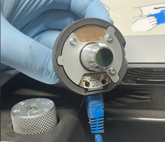
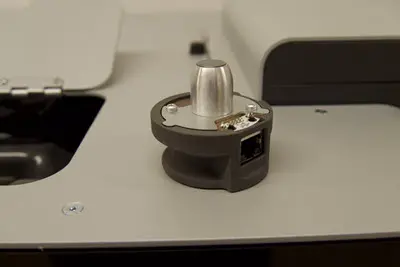
Open the access door to the IR sensor panel, located on top of the printer next to the hopper. Lift the IR sensor and disconnect the cable from it. Set the IR sensor aside on a flat surface with the sensor window facing up. Feed the IR sensor’s cable down through the plastic shroud.
Step 2: Remove the upper cooling shroud screws
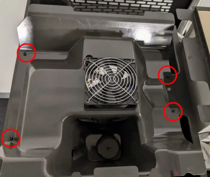
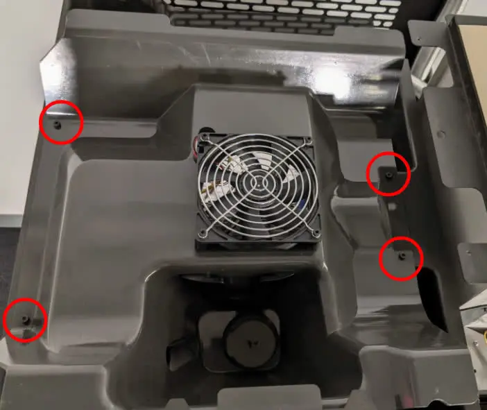
Using a 3 mm hex driver, loosen and remove the four 8 mm M4 socket head screws securing the upper cooling shroud to the printer. Do not yet separate the upper cooling shroud from the printer.
Step 3: Lift the upper cooling shroud
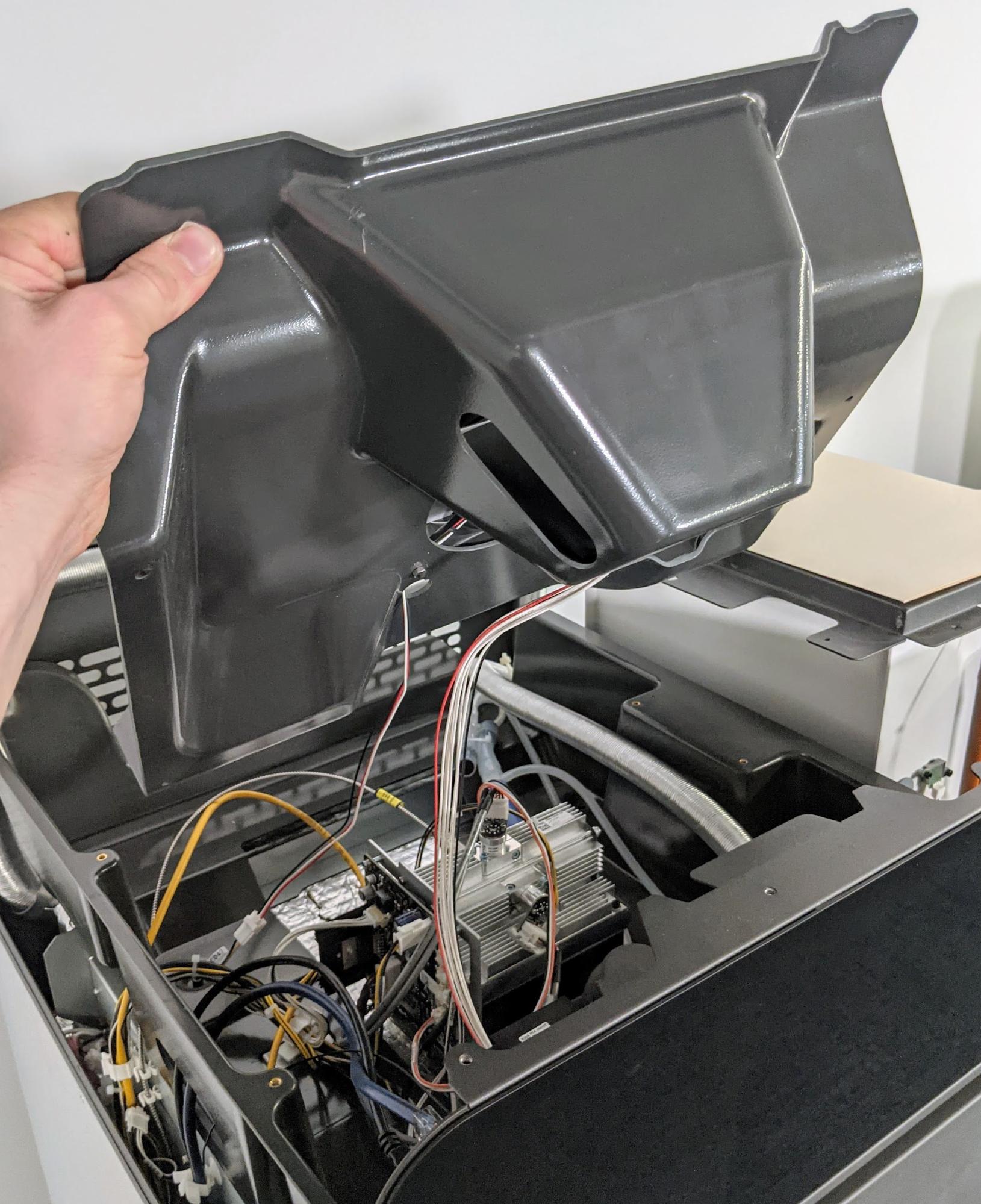
Gently lift up but do not separate the front edge of the plastic shroud from the top of the printer so that the cables attached to the shroud can be accessed.
Notice:
Take care when lifting the plastic shroud so as to not strain the cables attached to it.
Step 4: Unplug the fan cable
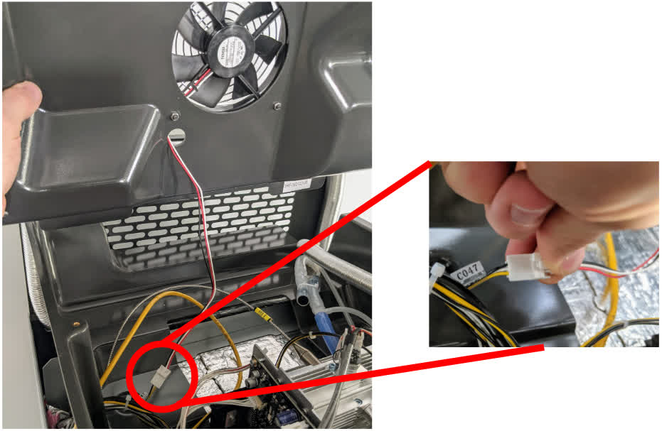
Disconnect the fan cable from the connector labeled C047 by squeezing on the plastic latch. Do not pull on the individual wires; only pull on the plastic connector.
Tip:
It may be helpful to have one person hold the plastic shroud while another person unplugs the cables.
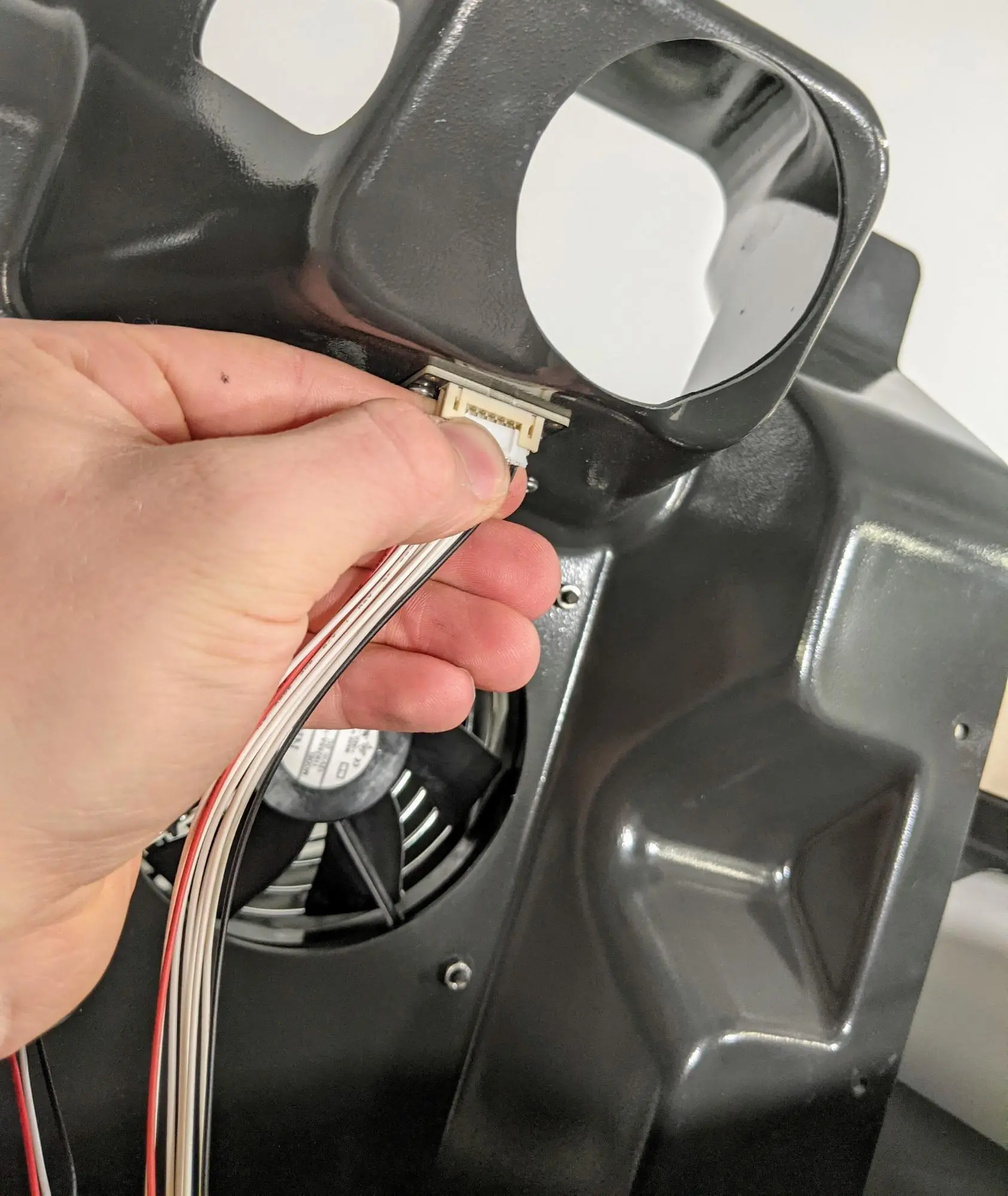
Unplug the RFID reader board cable from the circuit board by gently pulling on the white connector.
Separate the upper cooling shroud from the printer and set it aside.
Removing the original display assembly
Overview: Unplug and remove the original display assembly. Remove the motherboard from the display assembly to transfer to the replacement display assembly.
Step 1: Prepare to remove the display assembly
Put on an antistatic wrist band and connect it to a known ground point. Do not connect the wristband any surfaces that are powder-coated or painted.
Locate the motherboard, also known as the frontal lobe board or FoLoBo, mounted behind the display assembly.
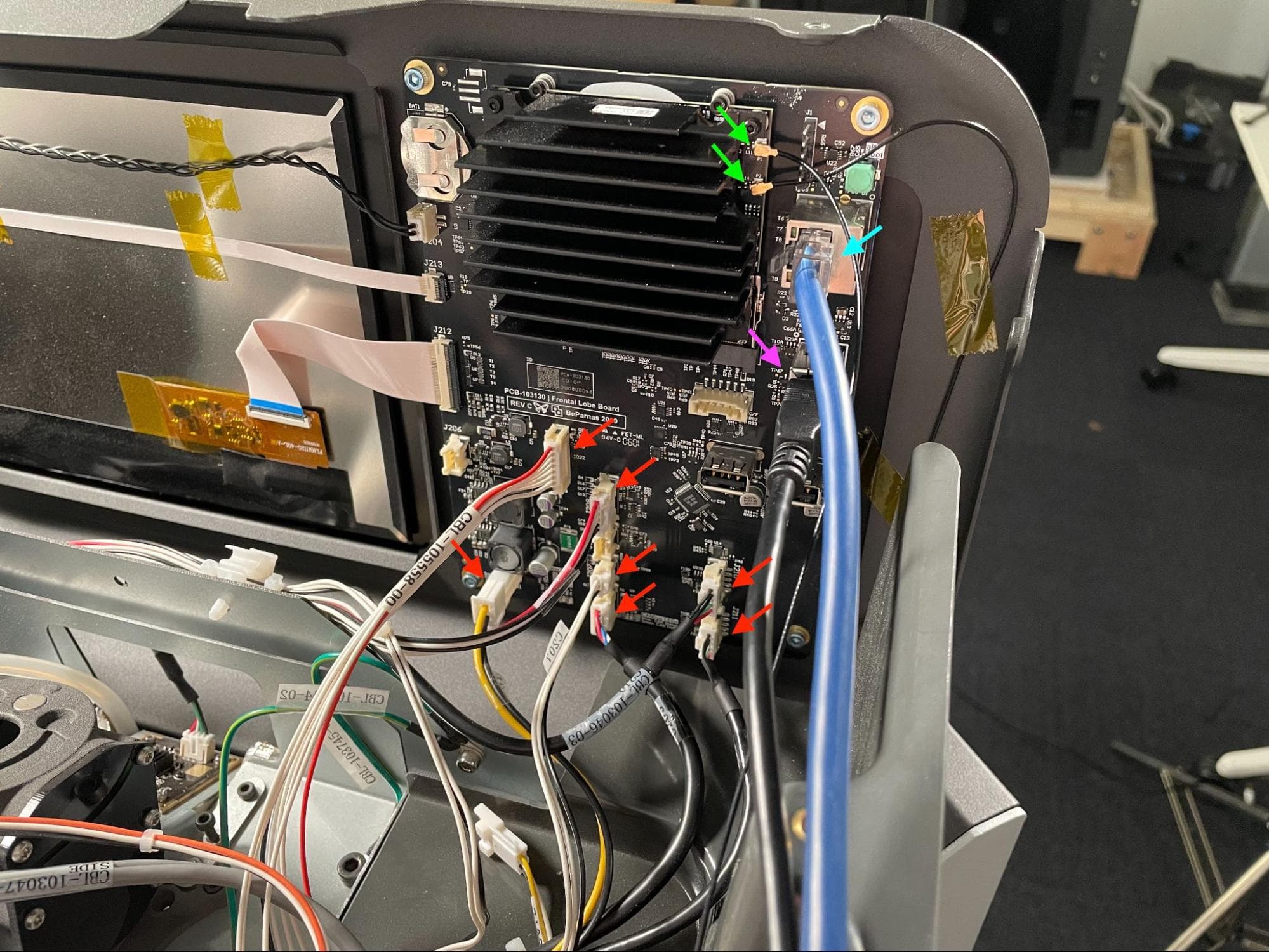
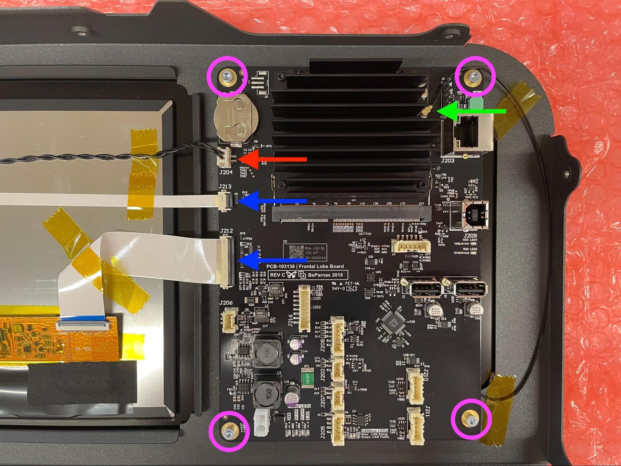
Begin disconnecting the USB, Ethernet, Wi-Fi, and JST connectors from the motherboard, as shown here. For cables that have a locking tab, make sure to disengage the locking tab first, then pull the connector away from the board via its plastic housing.
After disconnecting the RFID reader cable harness, set it aside. Leave all other cable harnesses inside the printer.
Note:
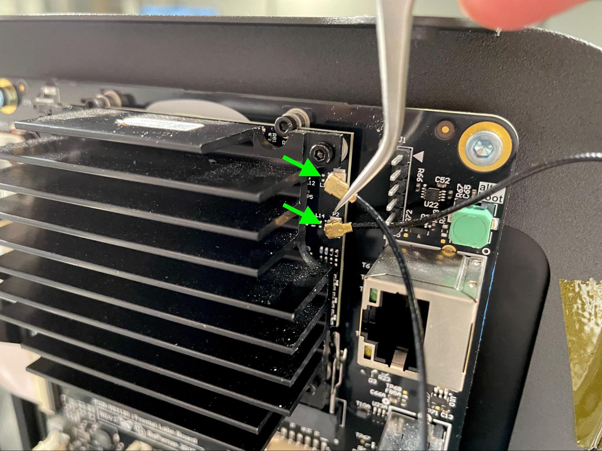
Use a pair of ESD-safe tweezers or a spudger to disconnect the Wi-Fi antenna cables. These connectors are extremely fragile and can easily bend or break if improperly handled. Older printers have two cables, while newer models have one.
Step 3: Open the print enclosure door
Open the filter cabinet door, then manually open the print enclosure door by pulling the blue release handle. This creates enough space to remove the display assembly.
Step 4: Remove the display assembly mounting screws
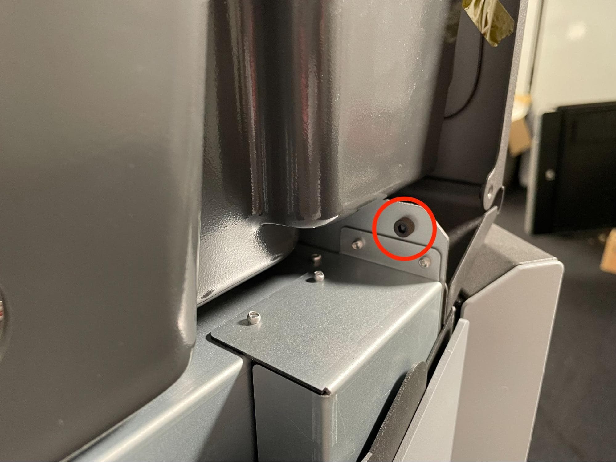
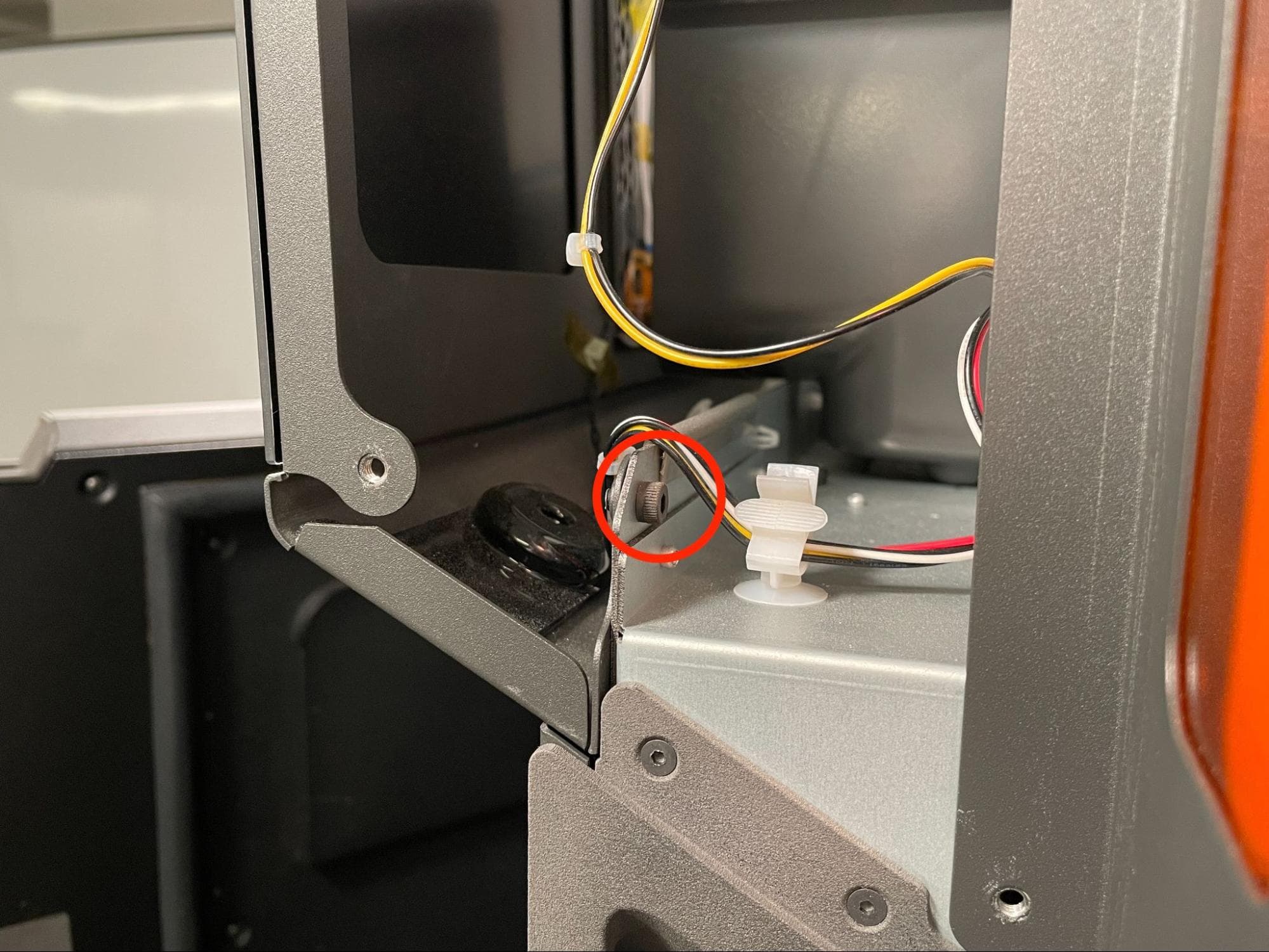
Locate the display assembly mounting screws, positioned at the bottom corners of the display. Using a 3 mm hex driver, loosen and remove the two 6 mm M4 black socket head screws holding the display assembly to the top of the printer.
The entire display assembly will be free once these screws are removed. Hold the assembly with one hand when removing the second screw.
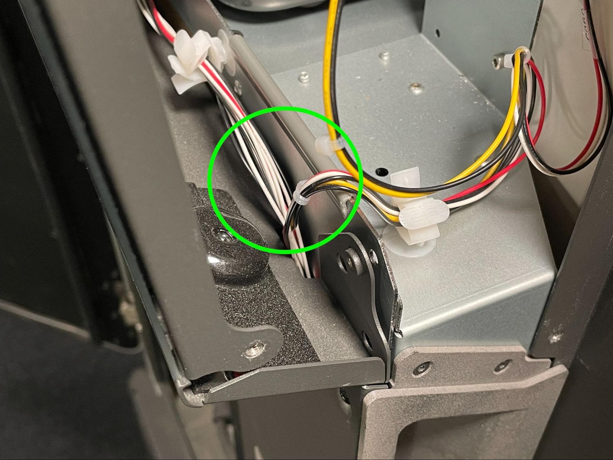
Carefully tip the display assembly forward and away from the printer. Make sure that you do not pinch or damage any of the wires around the display assembly, particularly the yellow, black, red and white cable harnesses just above the door handle.
Lay the display assembly glass-side down on a flat, clean surface.
With your antistatic wrist band still connected to a grounding point, disconnect the two ribbon cables and one JST connector (if present) from the left side of the motherboard. Note that newer printers do not have this JST connector.
If your printer has a Wi-Fi antenna cable running from the display assembly to the motherboard, disconnect it if you have not done so already.

Step 7: Separate the motherboard from the display assembly
Using a 2.5 mm hex driver, loosen and remove the four 8 mm M3 socket head screws securing the motherboard to the back of the display assembly. Set the screws aside. Carefully separate the motherboard from the display assembly and set it aside onto a flat, clean, anti-static surface.
Notice:
Do not place the motherboard onto carpet or non-grounded work surfaces as static discharges may damage it. If the motherboard is damaged during this procedure, the entire printer may need to be replaced.
Installing the replacement display assembly
Overview: Mount the motherboard to the new display assembly, then install the display assembly.
Step 1: Prepare the new display assembly
If you are not still wearing one, put on an antistatic wrist band and connect it to a known ground point. Unpack the new display assembly and lay it glass-side down on a flat, clean surface.
Tip:
Lay the display assembly on the ESD-safe plastic wrap it ships with.
Orient the motherboard with the heatsink facing up. Place it only the standoffs on the back of the display assembly, aligning the four screw holes in the motherboard with those in the standoffs. Ensure that no cables are trapped beneath the motherboard.
Thread one 8 mm M3 socket head screw into each of the four screw holes in the motherboard. Using a 2.5 mm hex driver, tighten until snug.
Reconnect the two ribbon cables to the motherboard, securing them in place with the locking latches. If one is present, reconnect the JST cable above the ribbon cables.
If a Wi-Fi antenna cable is present on the display assembly, connect it to the plug labeled P2. Note that newer printers and display assemblies do not have a second Wi-Fi antenna. If this is the case, leave the P2 plug empty.
Bring the display assembly up to the printer at an angle and align the tab at the bottom with the gap directly above the print enclosure door. Ensure that the yellow, back, white, and red cable harnesses are not being crushed by the tabs on the back of the display assembly.
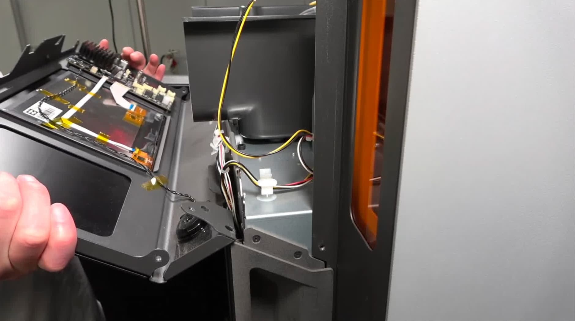
Step 5: Mount the display assembly
Pivot the display assembly back towards the top of the printer so the display’s flange tabs are flush with the corresponding flanges on the frame.
Thread one M4 socket head screw into both of the two screw holes in the bottom corners of the display assembly. Do not fully tighten.
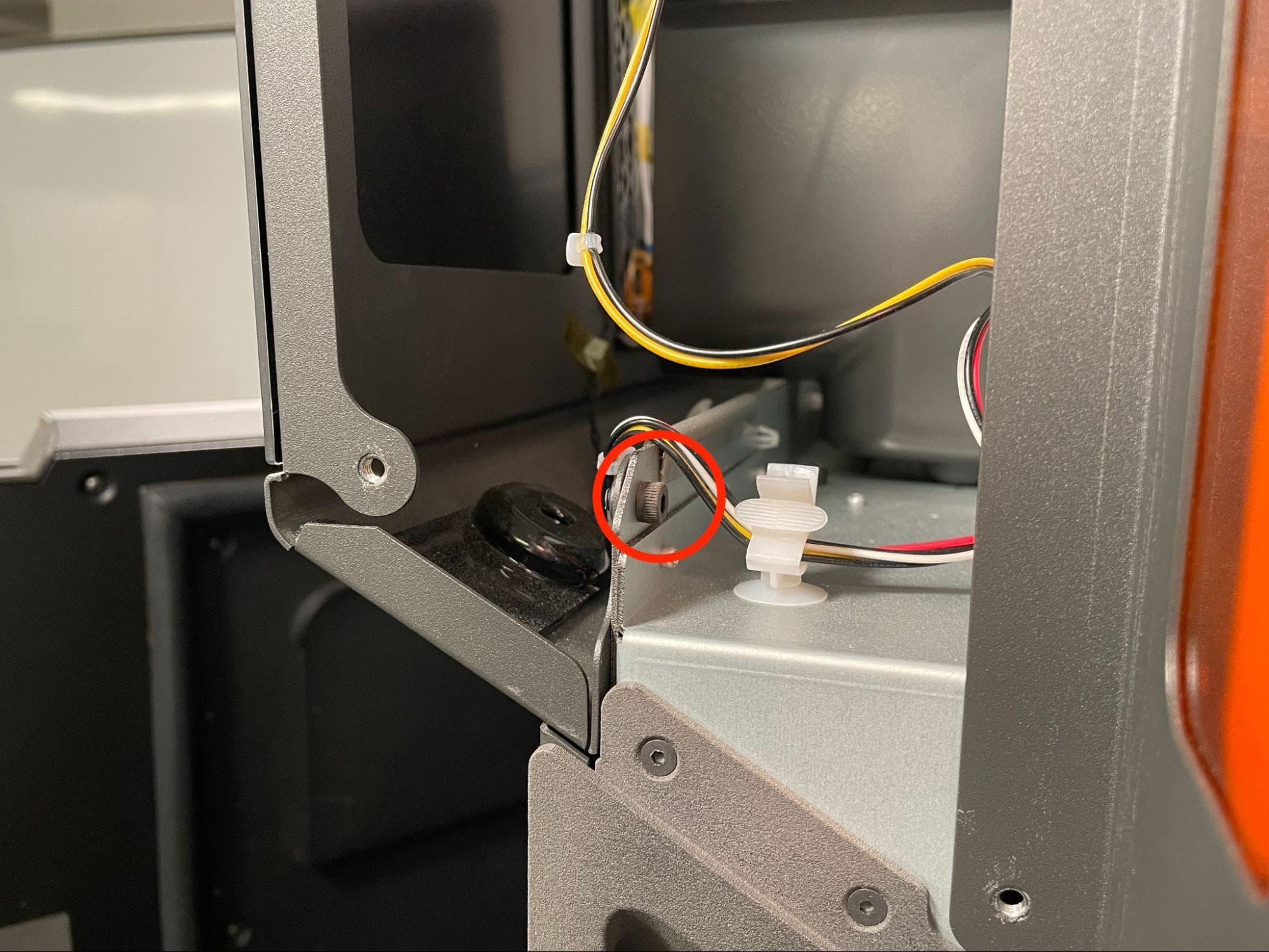
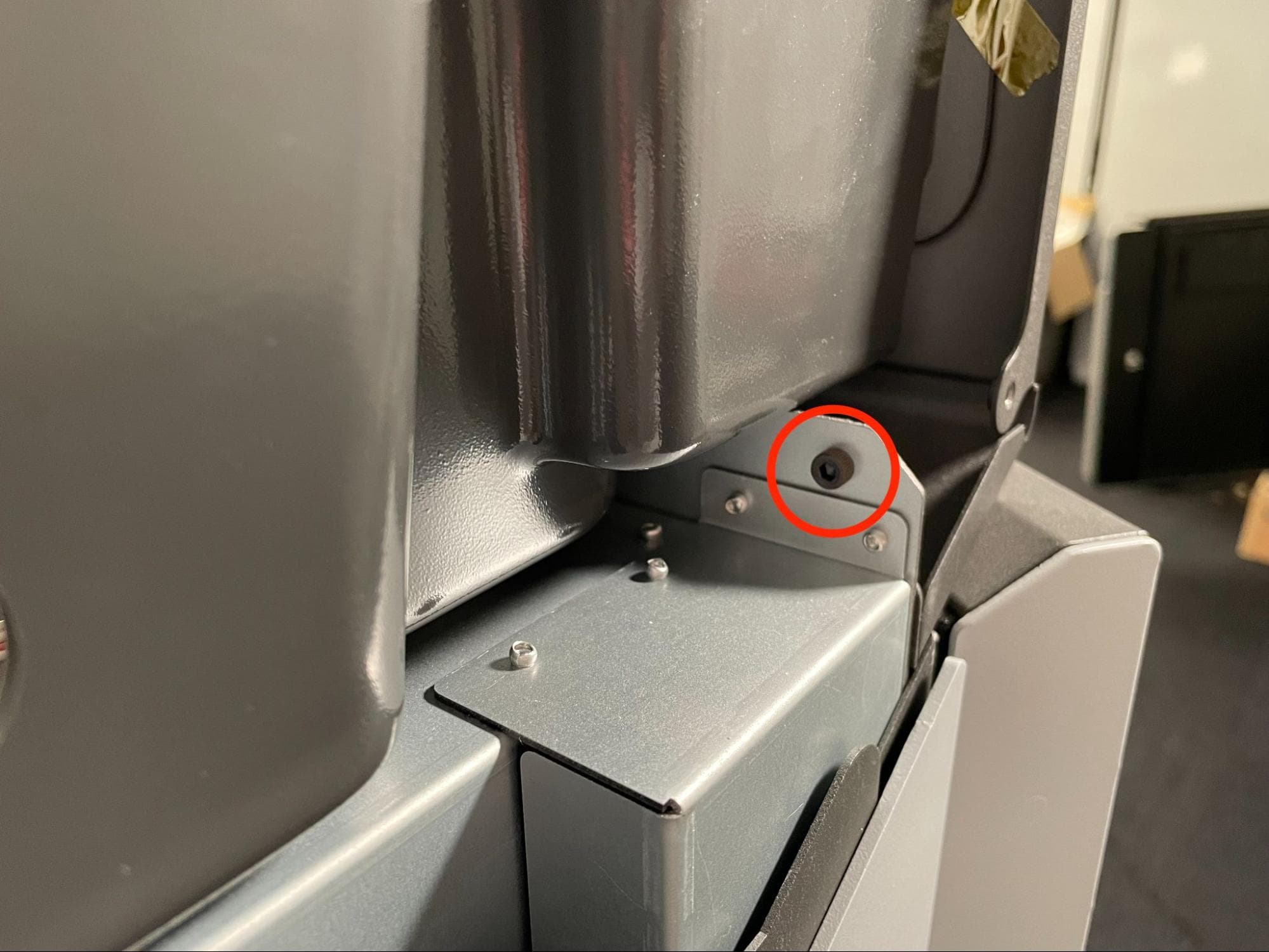
Step 6: Check the display assembly position
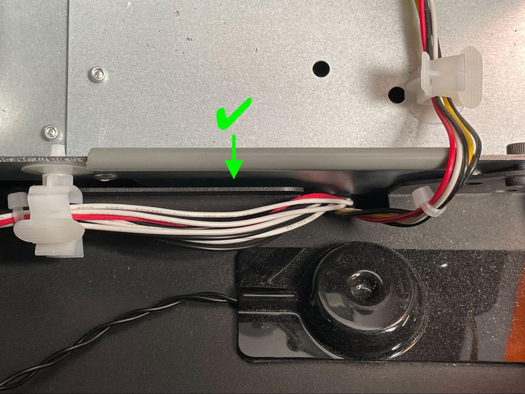

Check that none of the harnesses above the door handle are caught between the display assembly and printer’s frame.
Step 7: Secure the display assembly
Using a 3 mm hex driver, tighten the two 6 mm M4 black socket head screws until snug.
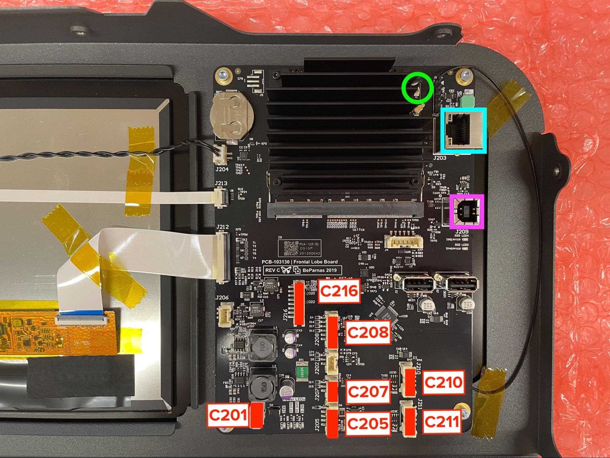
Reconnect the remaining cables to the motherboard: seven JST connectors (including the RFID reader cable harness you previous set aside), the Ethernet cable, the USB cable, and the Wi-Fi antenna cable. Refer to the image here to map each connector with its socket. Connect the Wi-Fi antenna cable to the upper plug labeled P1.
Reinstalling the upper cooling shroud
Overview: After replacing the display assembly, reinstall the upper cooling shroud.
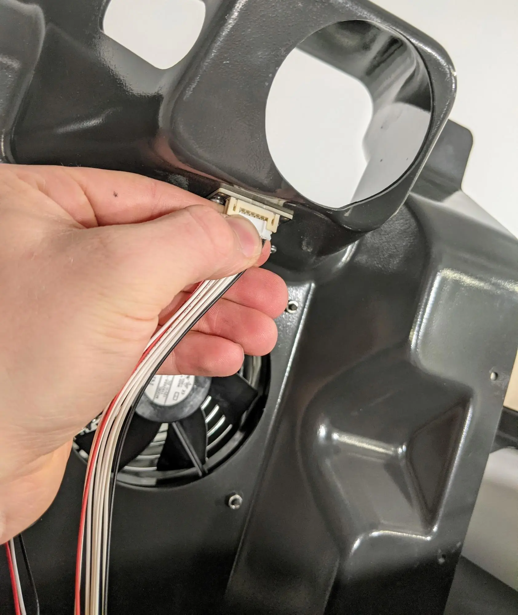
Hold the upper cooling shroud above the printer and plug the RFID reader cable connector into the RFID board by gently pushing it into the receptacle. The connector will only fit in one orientation.
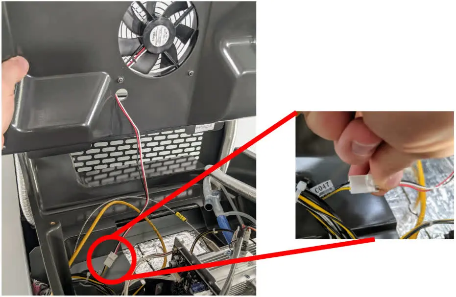
Reconnect the cooling fan connector to the socket labeled C047.
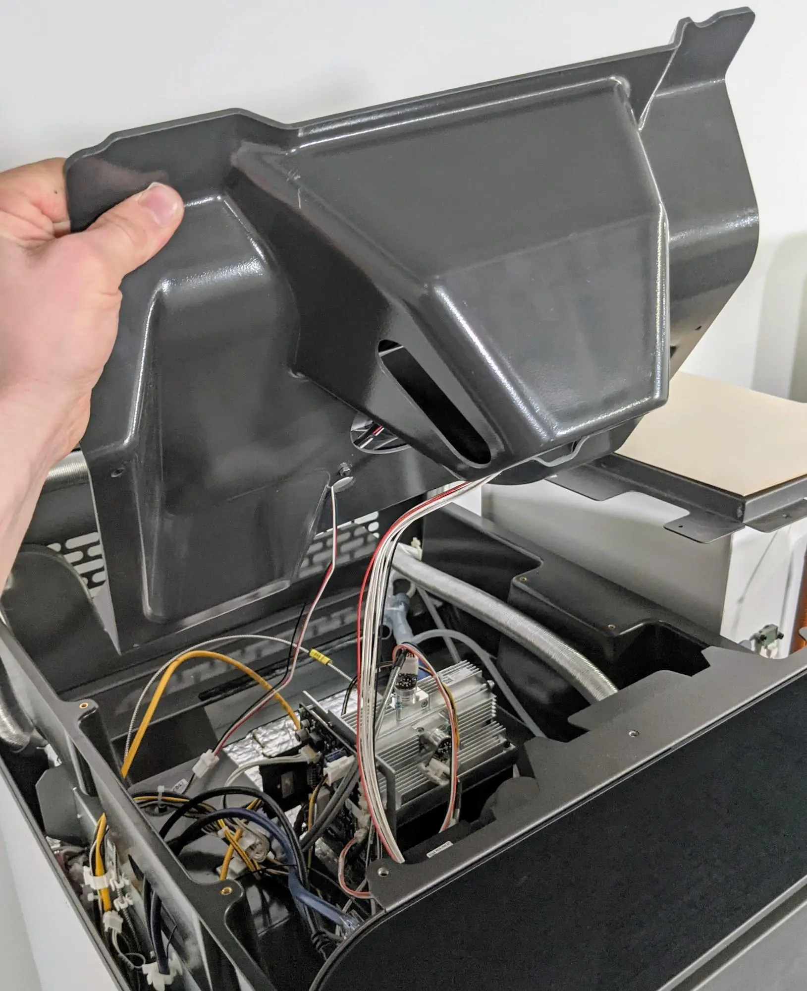
Position the top cooling shroud by holding it from the front edge so that the cables covered by the shroud can still be accessed. Feed the IR sensor’s Ethernet cable back through the cutout in the top shroud.
Step 4: Mount and secure the upper cooling shroud
Lower the upper cooling shroud on the printer, aligning the four screw holes in the shroud with the corresponding screw holes in the printer frame. Thread one 8 mm M4 socket head screw into each of the screw holes. Using a 3 mm hex driver, tighten until snug.
Step 5: Connect and mount the IR sensor
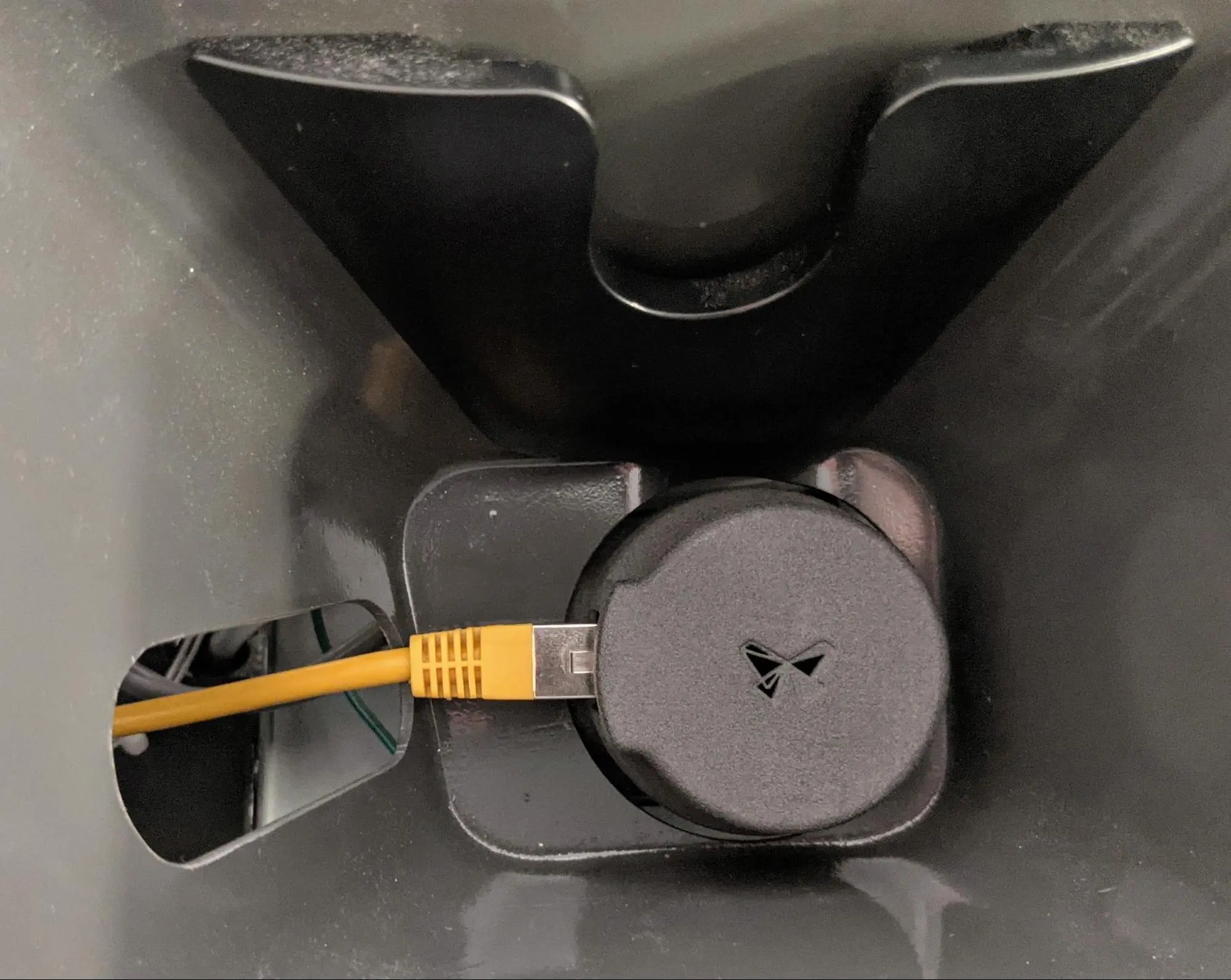
Inspect the IR sensor lens for debris and clean it if necessary. Attach the ethernet cable to the IR sensor, then place the sensor back into its mount.
Reinstalling the top panel
Overview: After installing the new display assembly, reinstall and secure the top panel.
Step 1: Align the top panel
Lift the top panel and place it on top of the printer. Align the screw holes in the top panel with the corresponding holes in the printer frame.
Step 2: Secure the top panel screws
Thread a 6 mm M4 countersunk screw into each of the 26 marked screw holes in the top panel:
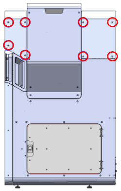
Using a 2.5 mm hex driver, tighten the screws until snug.
Finalizing the repair
Overview: After installing the replacement display assembly, power on the printer and perform final checks.
Step 1: Power on the printer
Connect the power cable to the printer and the power supply. The printer initializes.
Step 2: Test the repair
Navigate through the various menus on the printer touchscreen to make sure it responds correctly. Contact Formlabs Support or your certified service provider to share the results of the procedure.